Myo-20: Professional Motor Control for Robotics
Myo-20 is a compact, powerful motor control board designed for robotics research, student projects, and startup applications. Bring professional-grade motor control to your robotics platform with minimal setup.
Features
Multi-Protocol Communication
- USB (GUI control)
- CAN Bus (multi-motor, daisy-chainable)
- UART (Motor Pilot compatible)
- SWD (hardware debugging)
Three Control Modes
- Speed control (RPM)
- Torque control (current)
- Position control (angle)
Production-Ready Protection
- ESD protection on all external data lines
- Reverse polarity protection
- Inrush current limiting (soft start)
- Over-current thermal monitoring
- Encoder loss detection
FOC Algorithm
- Field-Oriented Control at 10 kHz
- <5% speed overshoot
- <5% torque ripple
- Full algorithm visibility for research
Flexible Encoder Support
- On-board quadrature encoder (up to 1024 PPR)
- External SPI encoder (AS5047p compatible)
- ABI external encoder support
Quick Start (10 Minutes)
Prerequisites
Hardware:
- Myo-20 integrated motor
- Teensy 4.1 microcontroller
- Power supply (24V or 48V, 10A+)
- USB cable (Teensy programming)
- Wiring (22-26 AWG recommended)
Software:
Step 1: Download necessary files from our website
On the same page as this document, download the files motor_interface.h, myo20_drivers.h, myo20_drivers.cpp, and example_main.cpp (if you want an example on how to use the library).
Step 2: Create a Teensy 4.1 Project
Follow a PlatformIO tutorial if this is your first time to create a project using the board of your choice, and drag the .h files into the include folder, and .cpp files into the src folder.
Step 3: Write the commands you want to send to the motor in your main.cpp
See example_main.cpp if you don't know how to start!
Step 4: Flash Teensy
Make sure nothing is connected to the Myo-20
Connect Teensy 4.1 via USB
Upload:
- Click Upload
- Press Teensy button if prompted
Monitor output:
- Tools → Serial Monitor
- Set baud rate to 115200
- Watch test sequence execute
Step 5: Connect Hardware
Safety First: Do this AFTER the Teensy is flashed.
Power off everything
Connect Myo-20 to Teensy:
- UART mode: Teensy pins 0/1 → Myo-20 pins 11/13
- CAN mode: Teensy pins 22/23 → CAN transceiver, CAN transceiver CANH/L → Myo-20 pins 3/1, or 6/4
- GND connections verified
Connect motor and encoder:
- 3-phase motor → Myo-20 phase outputs
- IF External Encoder: ABI & SPI connected
- Power supply → Myo-20 XT30 power connector
Power on:
- Turn on power supply (observe inrush limiting)
- Teensy should enumerate as USB device
- Motor should be stationary (safe state)
Test:
- Open serial monitor (USB)
- Watch test sequence
- Motor should execute commands smoothly
Documentation
For Getting Started
- PRODUCT_DOCUMENTATION.md - Complete guide with pinout, getting started example, API reference, and use cases (START HERE)
For Troubleshooting
For Development
For Advanced Topics
Architecture
Your Application
↓
Teensy 4.1 (Motor Driver Library)
├─ UART/ASPEP (Motor Pilot compatible)
└─ CAN Bus (multi-motor capable)
↓
Myo-20 Motor Control Board
├─ STM32G4 Microcontroller
├─ STSPIN32G4 Gate Driver
└─ 3-Phase Inverter
↓
3-Phase Motor + Encoder
| Metric |
UART |
CAN |
| Latency |
5-10 ms |
1-2 ms |
| Throughput |
150 cmd/sec |
500 cmd/sec |
| Handshake |
100-500 ms |
Instant |
| Multi-Motor |
No |
Yes (daisy-chain) |
| Best For |
Research |
Production |
Key Specifications
| Specification |
Value |
| Speed Range |
±3,000 RPM |
| Speed Resolution |
1 RPM |
| Torque Control |
Up to 150% rated current |
| FOC Loop Rate |
10 kHz |
| Encoder Support |
1024 PPR (on-board or SPI) |
| Power Supply |
24-48V DC |
| Board Dimensions |
82.2mm * 62.29mm |
| Connectors |
S20B-PHDSS (20-pin) |
| Mating Receptacle |
PHDR-20VS, SPHD-001T-P0.5 Crimped Ends #26 - 22 AWG |
Control Methods
Speed Ramp
motor.setSpeedRamp(target_rpm, ramp_time_ms);
motor.setSpeedRamp(2000, 1000); // 2000 RPM over 1 sec
Torque Ramp
motor.setTorqueRamp(target_iq, ramp_time_ms);
motor.setTorqueRamp(500, 500); // Ramp to 500 Iq over 500 ms
motor.setTorqueDirect(target_iq);
motor.setTorqueDirect(1000); // Step to 1000 Iq instantly
Position Control
motor.setPosition(target_rad, duration_sec);
motor.setPosition(3.1416f, 2.0f); // π radians in 2 seconds
Examples
Mobile Robot (2-Wheel Drive)
Myo20CAN left(0x100, 1000000);
Myo20CAN right(0x101, 1000000);
void loop() {
left.setSpeedRamp(1500, 500); // Forward
right.setSpeedRamp(1500, 500);
delay(3000);
left.setSpeedRamp(1000, 500); // Turn right
right.setSpeedRamp(500, 500);
delay(2000);
}
Force-Controlled Joint (with load feedback)
Myo20UART motor(&Serial1, 1843200);
void loop() {
float load = readLoadSensor();
float error = target_load - load;
int16_t torque = error * Kp;
motor.setTorqueRamp(torque, 100);
}
Multi-Joint Trajectory (exoskeleton)
Myo20CAN hip(0x100, 1000000);
Myo20CAN knee(0x101, 1000000);
Myo20CAN ankle(0x102, 1000000);
void loop() {
hip.setPosition(0.5f, 1.0f);
knee.setPosition(-0.3f, 1.0f);
ankle.setPosition(0.1f, 1.0f);
delay(1500);
}
See EXAMPLES.md for 10+ more examples.
Communication Modes
UART Mode (Motor Pilot Compatible)
- Protocol: ASPEP/MCP
- Baud Rate: 1.8432 Mbps (required!)
- Handshake: 100-500 ms
- Use Case: Research, single motor, Motor Pilot compatibility
Myo20UART motor(&Serial1, 1843200);
motor.begin();
delay(1500); // Wait for handshake
CAN Mode (Multi-Motor Ready)
- Protocol: CAN 2.0B, 1 Mbps
- Handshake: Instant
- Use Case: Production, multi-motor, low-latency
Myo20CAN motor(0x100, 1000000);
motor.begin(); // Ready immediately
Pinout
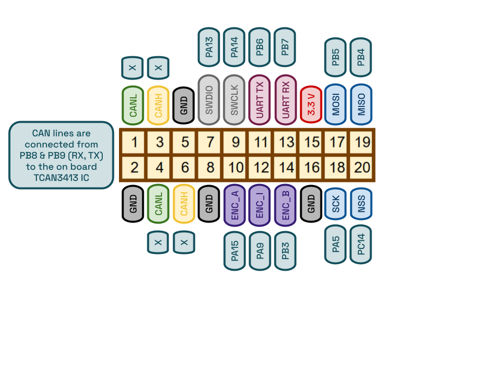
Main Connector (20-pin S20B-PHDSS)
Pin 1 - GND Pin 11 - MISO (SPI encoder)
Pin 2 - GND (return) Pin 12 - ENC_A (encoder)
Pin 3 - CANH Pin 13 - ENC_- (encoder index)
Pin 4 - CANL Pin 14 - ENC_B (encoder)
Pin 5 - SVDD10 Pin 15 - GND (encoder)
Pin 6 - GND (sense) Pin 16 - SCK (SPI encoder)
Pin 7 - UART_TX Pin 17 - VSS (motor ground)
Pin 8 - UART_RX Pin 18 - (reserved)
Pin 9 - 3.3V (sensor power) Pin 19 - PB5 (debug)
Pin 10 - MOS1 (debug) Pin 20 - PB4 (CS for SPI)
See PRODUCT_DOCUMENTATION.md for detailed wiring diagrams.
Troubleshooting
Motor doesn't respond?
- Check UART baud rate (must be 1843200!)
- Add delay(1500) after begin() for UART
- Verify wiring connections
- See TROUBLESHOOTING_GUIDE.md for complete guide
CAN not working?
- Check termination resistor (120Ω between CANH/CANL)
- Verify baud rate (1000000)
- Check connector polarity
- See TROUBLESHOOTING_GUIDE.md
Garbage text in serial?
- Wrong serial monitor baud rate? (should be 115200 for USB debug)
- Not using motor UART (Serial1) baud for debug serial
- See Troubleshooting section above
| Platform |
Support |
Status |
| Teensy 4.1 |
Primary |
Fully Supported |
| Arduino Uno |
UART only |
Limited (no CAN) |
| Arduino Mega |
UART only |
Limited (no CAN) |
| STM32 (Direct) |
Yes |
Coming Soon |
| Other MCUs |
Custom driver needed |
Not supported |
Getting Help
Documentation
Direct Support
Contributing
We welcome contributions!
- Found a bug?
- Have an example?
- Improve docs?
- Hardware improvement?
Open a support ticket with steps to recreate, or any of the above!
Specifications Summary
| Category |
Details |
| Microcontroller |
STM32G431VBTx (170 MHz, 512KB RAM) |
| Motor Driver |
STSPIN32G4 (integrated gate driver) |
| Main Processor |
Teensy 4.1 |
| Power Supply |
24-48V DC |
| Speed Range |
±3,000 RPM |
| Control Methods |
Speed, Torque, Direct Torque, Position |
| FOC Loop Rate |
10 kHz |
| Encoder |
1024 PPR (on-board or SPI) |
| Communication |
USB, CAN, UART |
| Protection |
ESD, Reverse polarity, Over-current, Thermal monitoring |
| Board Size |
82.2mm * 62.29mm |
| On Board Connector |
S20B-PHDSS (20-pin main) |
| Mating Receptacle |
PHDR-20VS, SPHD-001T-P0.5 Crimped Ends #26 - 22 AWG |
Roadmap
- Core motor control
- UART/CAN dual-mode
- Production firmware
- Complete documentation
- GUI control application (USB)
- Custom code guide (in progress)
- Hardware design guide (in progress)
- Multi-motor synchronization examples
- Telemetry interface (feedback to Teensy)
- Hardware v2.0 (improved thermal management)
FAQ
Q: Can I use this with Arduino Uno/Mega?
A: Limited support (UART only, no CAN). Teensy 4.1 recommended for full features.
Q: What's the minimum ramp time?
A: 0ms (step), but 500-2000ms recommended for smooth motion.
Q: Can I run multiple motors?
A: Yes! Use CAN mode with different CAN IDs (0x100, 0x101, 0x102...). UART mode supports single motor only.
Q: How do I debug issues?
A: See TROUBLESHOOTING_GUIDE.md. Most issues are UART baud rate or wiring. Otherwise, feel free to open a support ticket.
Q: Can I modify the firmware?
A: Yes! STM32 firmware is pre-flashed. Use STM32CubeIDE and Motor Control Workbench for customization. Custom code guide in progress.
Q: What's the encoder resolution?
A: 1024 PPR standard (0.35° resolution). External encoders supported, using SPI to detect and switching to ABI once detected.
Q: Is thermal protection automatic?
A: Yes. Firmware automatically limits current if motor gets hot. No user code needed.
Changelog
v1.0 (July 2026)
- Initial release
- UART/ASPEP protocol (Motor Pilot compatible)
- CAN bus support with daisy-chaining
- Speed, Torque, Position control
- Complete documentation
- 10+ working examples
- Comprehensive troubleshooting guide
- GUI control application (USB)
Quick Links
Ready to revolutionize your robotics?
Start with the Complete Getting Started Example
Get your Myo-20 motor control board working in 5 minutes!
Myo-20 - Professional Motor Control for Robotics Research | Made for Researchers, By Researchers
Power and current
Electrical ratings
| Parameter |
Value |
| Nominal bus voltage |
48 V DC |
| Operating range |
24–48 V DC |
| Nominal power |
80 W |
| Continuous current |
7 A |
| Peak current |
25 A |
| Phase-to-phase resistance |
0.439 Ω |
Do not exceed 48 V. The bus ceiling is set by the control board, not by the
motor windings, and there is no margin above it to borrow.
Sizing a supply
Size for the duty cycle you intend to run, not for the peak number.
- Continuous operation draws about 7 A. At 48 V that is roughly 340 W of
bus capacity per actuator, with headroom.
- Stall or hard acceleration pulls up to 25 A. A supply sized only for the
continuous figure will sag, and the drive will fault rather than brown out.
- Multiple joints rarely peak simultaneously, but sizing for all-peak is
the only assumption that is always safe. If you size below it, make that
choice deliberately.
A bench supply with a low current limit is the usual cause of a joint that
works unloaded and faults the moment it is asked to do anything.
Regeneration
A backdrivable actuator is a generator when the load drives it — lowering a
limb, absorbing an impact. That energy is pushed back onto the bus and lifts
its voltage.
Myo-20 integrates discharge circuitry to absorb it, which is why no external
regen clamp is required for basic protection. The clamp threshold and its
dissipation limit are not yet published — until they are, treat sustained
overhauling loads as unbounded and provide your own margin.
Battery-powered systems usually tolerate regeneration well, since the pack
absorbs it. A bench supply generally cannot sink current at all, and will
either trip or let the bus voltage climb.
Torque and speed
The envelope
| Parameter |
At the output |
| Continuous torque |
7.5 N·m |
| Peak torque |
20 N·m |
| Continuous speed |
110 rpm |
| Maximum speed |
320 rpm |
| Reduction |
8:1 planetary |
All torque and speed figures are at the output flange, after the 8:1
reduction — not at the rotor.
Continuous versus peak
The two numbers describe different things and are not interchangeable.
7.5 N·m continuous is what the actuator can hold indefinitely at 7 A
without exceeding its thermal limits. This is the design number.
20 N·m peak is available at peak phase current for short durations only,
and how short depends on ambient temperature, mounting, and how much heat the
housing can move.
A useful sanity check: peak is roughly 3× continuous. Any duty cycle that
spends significant time above 7.5 N·m needs a thermal argument behind it.
Speed and torque trade against each other
Above 110 rpm the actuator is outside its continuous rating and sustainable
torque falls. 320 rpm is the no-load ceiling; it is not available
simultaneously with meaningful torque.
A measured torque–speed curve is not yet published. Until one is, treat
the corner points above as the envelope and do not interpolate between them —
the real curve is not a straight line.
What backdrivability costs
An 8:1 reduction is low enough that the joint backdrives easily, which is the
point of a quasi-direct drive. The consequence is that it will not hold
position unpowered. A Myo-20 holding a load against gravity draws current the
entire time, and that current counts against the continuous rating.
If your application needs to hold a static load for long periods, budget for it
thermally, or design in a mechanical brake.
Myo-20 Motor Control Board
Professional Motor Control for Robotics
Overview
Myo-20 is a compact, powerful motor control board designed for robotics research, student projects, and startup applications. It brings professional-grade motor control to your robotics platform with minimal setup.
What You Get
- Multi-Protocol Communication: USB, CAN, UART, and SWD debugging
- Three Control Modes: Speed, Torque, and Position control
- Flexible Encoder Support: On-board encoder interface + optional external SPI encoder (uses ABI)
- Production-Ready Protection: ESD protection, reverse polarity protection, inrush current limiting
- Easy Integration: Works with Teensy 4.1, Arduino-compatible
Ideal For
✓ Robotics research platforms
✓ Undergraduate/graduate student projects
✓ Startup actuator development
✓ Educational motor control courses
✓ Unmanned systems (wheeled/legged robots, drones)
✓ Prosthetics and exoskeleton research
Key Features
Motor Control Capabilities
| Feature |
Specification |
| Control Modes |
Speed (RPM), Torque (Current), Position (Angle) |
| Speed Range |
±3,000 RPM |
| Speed Resolution |
1 RPM |
| Torque Range |
Up to 150% rated motor current |
| FOC Algorithm |
Full Field-Oriented Control at 10 kHz |
| Encoder Support |
On-board (quadrature), External SPI (AS5047p), ABI at 1024 PPR |
| Overshoot |
<5% (speed control) |
| Ripple |
<5% (FOC torque ripple) |
Communication
| Protocol |
Feature |
Use Case |
| USB |
GUI control, live parameter adjustment |
Development, visualization |
| CAN |
Multi-motor support, daisy-chainable termination |
Production systems, multi-joint robots |
| UART |
Motor Pilot compatible (1.8432 Mbps) |
Single motor, educational |
| SWD |
Hardware debugging with ST-Link |
Firmware development |
Protection & Reliability
✓ ESD Protection on all external data lines (USB, CAN, UART, SPI, SWD, ABI, 3.3V)
✓ Reverse Polarity Protection on motor supply
✓ Inrush Current Limiting (slow start to protect power supply)
✓ Over-Current Shutdown with thermal monitoring
✓ Encoder Loss Detection (closed-loop safety)
Board Features
| Component |
Details |
| Power Connector |
S20B-PHDSS(LF)(SN) - 20-pin main connector |
| Mating Receptacle |
PHDR-20VS |
| Crimped Ends |
SPHD-001T-P0.5 (#26 to #22 AWG) |
| Motor Supply |
24V-48V DC |
| Encoder Input |
Quadrature (on-board) or SPI & ABI (external) |
| CAN Termination |
Toggleable on-board resistor, daisy-chain capable |
| Dimensions |
82.2mm * 62.29mm |
Pinout & Connections
Main Connector (20-pin S20B-PHDSS)

Motor Power Connections
Three 3-phase motor outputs (PWM):
- Phase A, B, C to brushless DC motor windings
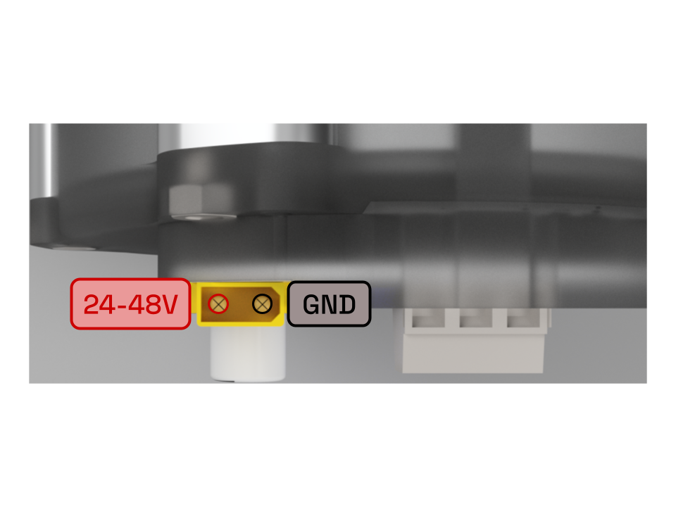
XT30 power connector:

Encoder Options
Option 1: On-Board Encoder (Quadrature)
No extra configuration needed
Option 2: External SPI Encoder (ABI)
Connect SPI and ABI pins to the 20-pin connector, along with 3V3 and GND
Communication Connectors
UART Connection (1.8432 Mbps)
Teensy 4.1 Pin 0 (RX1) ← Myo-20 Pin 11 (UART_TX)
Teensy 4.1 Pin 1 (TX1) → Myo-20 Pin 13 (UART_RX)
Teensy GND ← Myo-20 Pin 2, 5, 8, or 16 (GND)
CAN Connection (1 Mbps)
Needs external CAN transceiver for Teensy 4.1
Teensy 4.1 Pin 22 & 23 (CAN0_TX & RX) → CAN Transceiver
CAN Transceiver CANH → Myo-20 Pin 3 (CANH)
CAN Transceiver CANL → Myo-20 Pin 1 (CANL)
CAN Transceiver GND → Myo-20 Pin 2 (GND)
DAISY CHAIN
Myo-20 Pin 4, 5, 6 (CANL, CANH, GND) → other controller
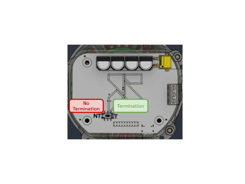
CAN Termination: If the Myo-20 is the end of the CAN bus, slide the switch to toggle a split 120Ω resistor between CANH and CANL. Slide the switch to the middle of the board to toggle termination resistors, away to disable
SWD Debugging
ST-Link → Myo-20
SWDCLK → Myo-20 Pin 9 (SCK)
SWDIO → Myo-20 Pin 7 (SWDIO)
GND → Myo-20 Pin 2, 5, 8, or 16 (GND)
3V3 → Myo-20 Pin 15 (3V3) (if needed)
Requires external power, 24-48V XT30
Getting Started (Complete Example)
This section walks you through setting up a basic motor control project from start to finish.
Prerequisites
Hardware:
- Myo-20 integrated motor
- Teensy 4.1 microcontroller
- Power supply (24V or 48V, 10A+)
- USB cable (Teensy programming)
- Wiring (22-26 AWG recommended)
Software:
Step 1: Download necessary files from our website
On the same page as this document, download the files motor_interface.h, myo20_drivers.h, myo20_drivers.cpp, and example_main.cpp (if you want an example on how to use the library).
Step 2: Create a Teensy 4.1 Project
Follow a PlatformIO tutorial if this is your first time to create a project using the board of your choice, and drag the .h files into the include folder, and .cpp files into the src folder.
Step 3: Write the commands you want to send to the motor in your main.cpp
See example_main.cpp if you don't know how to start!
Step 4: Flash Teensy
Make sure nothing is connected to the Myo-20
Connect Teensy 4.1 via USB
Upload:
- Click Upload
- Press Teensy button if prompted
Monitor output:
- Tools → Serial Monitor
- Set baud rate to 115200
- Watch test sequence execute
Step 5: Connect Hardware
Safety First: Do this AFTER the Teensy is flashed.
Power off everything
Connect Myo-20 to Teensy:
- UART mode: Teensy pins 0/1 → Myo-20 pins 11/13
- CAN mode: Teensy pins 22/23 → CAN transceiver, CAN transceiver CANH/L → Myo-20 pins 3/1, or 6/4
- GND connections verified
Connect motor and encoder:
- 3-phase motor → Myo-20 phase outputs
- IF External Encoder: ABI & SPI connected
- Power supply → Myo-20 XT30 power connector
Power on:
- Turn on power supply (observe inrush limiting)
- Teensy should enumerate as USB device
- Motor should be stationary (safe state)
Test:
- Open serial monitor (USB)
- Watch test sequence
- Motor should execute commands smoothly
| Metric |
UART Mode |
CAN Mode |
| Latency (end-to-end) |
5-10 ms |
1-2 ms |
| Command Throughput |
~150 cmd/sec |
~500 cmd/sec |
| Speed Response Time |
10 ms |
10 ms |
| Torque Response Time |
100 μs |
100 μs |
| FOC Loop Rate |
10 kHz |
10 kHz |
Power Consumption
| State |
Current (Teensy) |
Current (Myo-20) |
| Idle (no motor) |
~50 mA |
~20 mA |
| UART Active |
~80 mA |
~25 mA |
| CAN Active |
~70 mA |
~25 mA |
| Motor Running |
~80 mA |
+ motor current |
(Teensy powered by USB, Myo-20 at 24V motor supply)
| Protocol |
Throughput |
Latency |
Handshake |
| UART |
1.8432 Mbps |
5-10 ms |
100-500 ms (ASPEP) |
| CAN |
1 Mbps |
1-2 ms |
Instant |
| USB |
480 Mbps |
Variable |
Instant |
Control Methods
Speed Control
Use For: Motor speed regulation, velocity commands
motor.setSpeedRamp(target_rpm, ramp_time_ms);
// Example: Accelerate to 2000 RPM over 2 seconds
motor.setSpeedRamp(2000, 2000);
Parameters:
target_rpm: -10,000 to +10,000 (negative = reverse)
ramp_time_ms: 0-65,535 milliseconds
Characteristics:
- Smooth acceleration (trapezoid profile)
- Encoder feedback (closed-loop)
- Typical overshoot: <5%
- Resolution: 1 RPM
Torque (Current) Control
Use For: Force control, impedance control, load regulation
motor.setTorqueRamp(target_iq, ramp_time_ms);
// Example: Ramp to 500 Iq over 500 ms
motor.setTorqueRamp(500, 500);
Parameters:
target_iq: Motor current reference in internal units (typical: ±2000)
ramp_time_ms: 0-65,535 milliseconds
Characteristics:
- Current regulation loop at 10 kHz
- Ripple: <5% via FOC algorithm
- Proportional to motor torque
- Use with load sensors for feedback
Use For: Step responses, high-speed feedback control, emergency stop
motor.setTorqueDirect(target_iq);
// Example: Step to 1000 Iq immediately
motor.setTorqueDirect(1000);
Parameters:
target_iq: Motor current (immediate, no ramp)
Characteristics:
- <1 microsecond response
- No ramp time
- Use for safety (zeroing):
motor.setTorqueDirect(0);
Position Control
Use For: Absolute positioning, joint angle control, trajectory execution
motor.setPosition(target_rad, duration_sec);
// Example: Move to π/2 radians (90°) in 2 seconds
motor.setPosition(1.5708f, 2.0f);
Parameters:
target_rad: Target angle in radians (-∞ to +∞)
duration_sec: Movement time in seconds
Common Angles:
- 0 radians = 0°
- π/2 radians ≈ 1.5708 = 90°
- π radians ≈ 3.1416 = 180°
- 2π radians ≈ 6.2832 = 360°
Characteristics:
- Absolute position (requires encoder)
- Trapezoidal velocity profile
- Encoder resolution-dependent accuracy
- Requires position control mode enabled on STM32
API Reference
Class: Myo20UART
UART communication with Motor Pilot protocol (1.8432 Mbps)
Constructor
Myo20UART(HardwareSerial *serial, unsigned long baud);
Methods
void begin(); // Initialize, start handshake
void setSpeedRamp(int16_t rpm, uint16_t ms); // Ramp speed
void setTorqueRamp(int16_t iq, uint16_t ms); // Ramp torque
void setTorqueDirect(int16_t iq); // Step torque
void setPosition(float rad, float sec); // Position control
Class: Myo20CAN
CAN bus communication (1 Mbps)
Constructor
Myo20CAN(uint32_t can_id, uint32_t baud_rate);
Methods
void begin(); // Initialize CAN
void setSpeedRamp(int16_t rpm, uint16_t ms); // Ramp speed
void setTorqueRamp(int16_t iq, uint16_t ms); // Ramp torque
void setTorqueDirect(int16_t iq); // Step torque
void setPosition(float rad, float sec); // Position control
Interface: IMotorController
Both Myo20UART and Myo20CAN implement this interface:
class IMotorController {
public:
virtual void begin() = 0;
virtual void setSpeedRamp(int16_t rpm, uint16_t ms) = 0;
virtual void setTorqueRamp(int16_t iq, uint16_t ms) = 0;
virtual void setTorqueDirect(int16_t iq) = 0;
virtual void setPosition(float rad, float sec) = 0;
};
Allows code to work with either protocol!
IMotorController *motor = new Myo20CAN(0x100, 1000000);
motor->begin();
motor->setSpeedRamp(1500, 1000); // Works regardless of protocol
Common Use Cases
Use Case 1: Wheel Motor (Mobile Robot)
Goal: Control wheel speed independently
Myo20CAN left_wheel(0x100, 1000000);
Myo20CAN right_wheel(0x101, 1000000);
void setup() {
left_wheel.begin();
right_wheel.begin();
}
void loop() {
// Drive forward
left_wheel.setSpeedRamp(1500, 500);
right_wheel.setSpeedRamp(1500, 500);
delay(3000);
// Turn right (right slower)
left_wheel.setSpeedRamp(1500, 500);
right_wheel.setSpeedRamp(750, 500);
delay(2000);
// Stop
left_wheel.setSpeedRamp(0, 500);
right_wheel.setSpeedRamp(0, 500);
delay(1000);
}
Use Case 2: Joint with Force Feedback (Robotic Arm)
Goal: Control joint with load cell feedback
Myo20UART motor(&Serial1, 1843200);
const float Kp = 50.0; // Proportional gain
void setup() {
Serial.begin(115200);
motor.begin();
delay(1500);
}
void loop() {
// Read load sensor (example: analog input)
float load = analogRead(A0) * (100.0 / 1023.0); // 0-100N range
// Target load
float target = 50.0; // 50N
// Simple feedback control
float error = target - load;
int16_t current_cmd = (int16_t)(error * Kp);
current_cmd = constrain(current_cmd, -2000, 2000); // Safety limits
// Apply current command
motor.setTorqueRamp(current_cmd, 100);
// Log feedback
Serial.print("Load: ");
Serial.print(load);
Serial.print(" N, Current: ");
Serial.println(current_cmd);
delay(50); // 20 Hz control loop
}
Use Case 3: Multi-Joint Trajectory (Exoskeleton)
Goal: Execute smooth trajectory across multiple joints
Myo20CAN hip(0x100, 1000000);
Myo20CAN knee(0x101, 1000000);
Myo20CAN ankle(0x102, 1000000);
struct Waypoint {
float hip_rad, knee_rad, ankle_rad;
float duration_sec;
};
const Waypoint gait[] = {
{0.0f, 0.0f, 0.0f, 0.5f},
{0.5f, -0.3f, 0.1f, 0.5f},
{0.3f, -0.5f, 0.2f, 0.5f},
{-0.2f, -0.2f, 0.0f, 0.5f},
{0.0f, 0.0f, 0.0f, 0.5f},
};
void setup() {
hip.begin();
knee.begin();
ankle.begin();
}
void loop() {
for (const auto &wp : gait) {
hip.setPosition(wp.hip_rad, wp.duration_sec);
knee.setPosition(wp.knee_rad, wp.duration_sec);
ankle.setPosition(wp.ankle_rad, wp.duration_sec);
delay((uint32_t)(wp.duration_sec * 1000) + 100);
}
}
Troubleshooting
Motor Doesn't Respond
Check 1: UART Baud Rate (if using UART)
- MUST be exactly 1843200 (not 115200!)
- If incorrect, motor will not respond
// WRONG:
Myo20UART motor(&Serial1, 115200); // ✗ Won't work
// CORRECT:
Myo20UART motor(&Serial1, 1843200); // ✓ Required
Check 2: UART Handshake (if using UART)
- Must wait for ASPEP handshake to complete
- Typical wait: 1-2 seconds
motor.begin();
delay(1500); // Critical! Don't skip this
motor.setSpeedRamp(1500, 1000);
Check 3: Wiring
- UART: Teensy pins 0/1 connected to Myo-20?
- CAN: Transceiver and termination resistors connected?
- GND connections complete?
Check 4: Motor Power
- Is motor supply powered on? (Blue light)
Check 5: Encoder Connection
- Encoder A/B/I connected to pins 10/14/12?
- Encoder power connected?
- Try with motor unloaded first
Solution Path:
- Try CAN mode (simpler, no handshake)
- Check baud rate (UART only)
- Verify wiring with multimeter
- Test encoder separately
- See COMPLETE_TROUBLESHOOTING guide
No Serial Connection
Symptom: Arduino IDE can't find Teensy
Solution:
- Press Teensy physical button
- Arduino IDE should show "Teensy Loader"
- Click "Upload"
- Reinstall Teensy drivers if needed
Garbage Text in Serial Monitor
Symptom: Weird characters instead of readable text
Cause: Wrong serial port or baud rate
Serial Monitor Settings:
- Port: /dev/ttyACM0 or COM3 (check which Teensy is on)
- Baud Rate: 115200 (for USB debug)
- NOT the motor UART (that's Serial1 at 1843200)
Motor Spins Wrong Speed
Causes:
- Encoder not connected → motor free-spins with no feedback
- Encoder polarity reversed → speed calculation inverted
- Encoder PPR wrong in firmware (should be 1024 for standard)
- Current limited → motor can't reach target
Checks:
- Verify encoder connections
- Swap encoder A/B if polarity wrong
- Check STM32 firmware encoder config
- Monitor current in debugger
Motor Jerks or Oscillates
Cause: FOC tuning parameters (less common with default settings)
Solution:
- Increase ramp time for smoother acceleration
- Check encoder noise (add RC filters if needed)
- Verify power supply stability
CAN Bus Error
Symptom: CAN messages not received
Checks:
- Termination resistor installed (120Ω)?
- Only at END of bus chain?
- Baud rate matches (1 Mbps)?
- Wiring correct (CANH/CANL)?
Solution:
// Check CAN transceiver
if (CAN0.errorCountRX() > 100) {
CAN0.reset(); // Reset CAN interface
delay(100);
}
Connection Drops (UART Mode)
Symptom: Motor responds initially, then stops
Cause: ASPEP watchdog timeout (need keepalive)
Solution: Send command every 1 second
unsigned long last_cmd = 0;
void loop() {
if (millis() - last_cmd > 1000) {
motor.setSpeedRamp(current_speed, 100); // Keepalive
last_cmd = millis();
}
}
Speed Control
motor.setSpeedRamp(2000, 1000); // 2000 RPM over 1 second
| Metric |
Typical Value |
| Time to 90% target |
900 ms |
| Overshoot |
<5% |
| Settling time |
1.1 sec |
| Steady-state error |
0 RPM |
Torque Control
motor.setTorqueRamp(1000, 500); // 1000 Iq over 500 ms
| Metric |
Typical Value |
| Rise time (10%-90%) |
450 ms |
| Peak overshoot |
<5% |
| Ripple (FOC) |
<5% |
| Current accuracy |
±1% |
Position Control
motor.setPosition(3.1416f, 2.0f); // π radians in 2 seconds
| Metric |
Typical Value |
| Position accuracy |
±1 encoder count |
| Settling time |
2.0-2.1 sec |
| Overshoot |
<2° |
| Resolution |
1024 PPR (0.35°) |
Feature Comparison Matrix
| Feature |
UART |
CAN |
USB |
| Single Motor |
✓ |
✓ |
✓ |
| Multi-Motor |
✗ |
✓ |
✗ |
| Handshake |
Yes (500ms) |
No (instant) |
Yes (100ms) |
| Throughput |
150 cmd/s |
500 cmd/s |
Limited |
| Latency |
5-10 ms |
1-2 ms |
Variable |
| Daisy Chain |
No |
✓ (with term.) |
No |
| Debugger |
No |
No |
No |
| Live Tuning |
Limited |
Limited |
✓ (GUI) |
| Range |
10-50 feet |
100+ feet |
5 feet |
| Best For |
Research |
Production |
Development |
Next Steps
After Getting Started
- Explore Examples: See EXAMPLES.md
- Read Full API Reference: See API_REFERENCE.md
- Custom Implementation: See
CUSTOM_CODE_GUIDE.md (coming soon)
- Contribute: Submit support tickets
Support
Documentation:
Hardware Support:
Version 1.0 | Last Updated: July 2026
Ready to revolutionize your robotics projects? Start with the Getting Started section above! 🚀
Myo-20 Protocol Reference
Technical protocol details for UART/ASPEP and CAN Bus communication.
Table of Contents
- UART/ASPEP Protocol (Motor Pilot)
- CAN Protocol
- Handshake Sequences
- Message Format Details
- Error Handling
- Timing Specifications
UART/ASPEP Protocol (Motor Pilot)
Overview: ASPEP (Asynchronous Serial Protocol for Easy Protocols) is the Motor Pilot protocol used for UART communication with Myo-20.
Layer Architecture
Application Layer
↓
MCP (Motor Control Protocol) - Callbacks, command routing
↓
ASPEP (Transport Layer) - Frame formatting, CRC, handshake
↓
UART Physical Layer (1.8432 Mbps)
Physical Layer
| Parameter |
Value |
| Baud Rate |
1843200 bps (fixed) |
| Data Bits |
8 |
| Stop Bits |
1 |
| Parity |
None |
| Flow Control |
None |
| Pins |
Teensy 0 (RX), Pin 1 (TX) |
Frame Structure
ASPEP frames are 4-byte header + optional payload + data
┌─────────────────────────────────────────┐
│ ASPEP Frame │
├──────────┬──────────┬──────────────────┤
│ Sync(4b) │ Len(12b) │ CRC-4(4b) │Payload
├──────────┴──────────┴──────────────────┤
│ 4 bytes ASPEP header │ 0-N bytes data │
└────────────────────────────────────────┘
Byte 0-3 form 32-bit header:
Bit 31-28: Sync = 0xA (async data packet)
Bit 27-16: Length = payload length (12 bits, 0-4095)
Bit 15-12: CRC-4 = checksum (4 bits)
Big Endian (MSB first):
uint32_t header = 0;
header |= (0xA << 28); // Sync = 0xA
header |= ((payload_len & 0xFFF) << 16); // Length
header |= (crc4_value & 0x0F); // CRC-4
// Transmit as bytes:
uint8_t b0 = (header >> 24) & 0xFF; // MSB
uint8_t b1 = (header >> 16) & 0xFF;
uint8_t b2 = (header >> 8) & 0xFF;
uint8_t b3 = (header >> 0) & 0xFF; // LSB
CRC-4 Calculation
Polynomial: x^4 + x + 1 (0x3)
uint8_t crc4_lookup_8[256] = {
0x0, 0x7, 0xE, 0x9, 0x5, 0x2, 0xB, 0xC,
0xA, 0xD, 0x4, 0x3, 0xF, 0x8, 0x1, 0x6,
// ... (full table in implementation)
};
uint8_t crc4_lookup_4[16] = {
0x0, 0x7, 0xE, 0x9, 0x5, 0x2, 0xB, 0xC,
0xA, 0xD, 0x4, 0x3, 0xF, 0x8, 0x1, 0x6
};
uint8_t compute_crc4(uint32_t data) {
uint8_t crc = 0;
crc = crc4_lookup_8[crc ^ ((data >> 24) & 0xFF)];
crc = crc4_lookup_8[crc ^ ((data >> 16) & 0xFF)];
crc = crc4_lookup_8[crc ^ ((data >> 8) & 0xFF)];
crc = crc4_lookup_4[crc ^ (data & 0x0F)];
return crc & 0x0F;
}
MCP (Motor Control Protocol) Command
Payload Structure:
Byte 0: Command Indicator (0x01 for MCP)
Byte 1: [Callback_ID(3b) | Reserved(5b)]
Byte 2-N: Command-specific data
Callback IDs:
| ID |
Command |
Data Format |
| 0 |
Speed Ramp |
[RPM_H, RPM_L, MS_H, MS_L] = 4 bytes |
| 1 |
Torque Ramp |
[IQ_H, IQ_L, MS_H, MS_L] = 4 bytes |
| 2 |
Position |
[RAD_0-3, DUR_0-3] = 8 bytes (IEEE float × 2) |
| 3 |
Direct Torque |
[IQ_H, IQ_L] = 2 bytes |
Command Payload Details
Speed Ramp (ID 0)
Bytes 0-1: Target RPM (int16_t, big-endian)
Range: -10,000 to +10,000
Example: 1500 RPM = 0x05DC (big-endian: 0x05, 0xDC)
Bytes 2-3: Ramp time (uint16_t, big-endian, milliseconds)
Range: 0 to 65,535 ms
Example: 1000 ms = 0x03E8 (big-endian: 0x03, 0xE8)
Example Frame (1500 RPM over 1000 ms):
ASPEP Header (4 bytes): Sync=A, Len=6, CRC=?
0xA6??
MCP Command (6 bytes):
0x01 // MCP indicator
0x00 // Callback 0 (Speed Ramp)
0x05 0xDC // 1500 RPM
0x03 0xE8 // 1000 ms
Total: 10 bytes transmitted
Torque Ramp (ID 1)
Bytes 0-1: Target Iq (int16_t, big-endian)
Range: -32,768 to +32,767
Example: 1000 Iq = 0x03E8
Bytes 2-3: Ramp time (uint16_t, big-endian, milliseconds)
Example Frame (1000 Iq over 500 ms):
ASPEP Header (4 bytes): Sync=A, Len=6, CRC=?
MCP Command (6 bytes):
0x01 // MCP
0x08 // Callback 1 (Torque Ramp)
0x03 0xE8 // 1000 Iq
0x01 0xF4 // 500 ms
Position Command (ID 2)
Bytes 0-3: Target position (float, IEEE 754)
Range: Any value (continuous)
Example: π ≈ 3.14159f
Bytes 4-7: Duration (float, IEEE 754, seconds)
Range: 0.0 to ~100.0 seconds
Example: 2.0 seconds
Example Frame (π radians in 2 seconds):
ASPEP Header (4 bytes): Sync=A, Len=10, CRC=?
MCP Command (10 bytes):
0x01 // MCP
0x10 // Callback 2 (Position)
0x40 0x49 0x0F 0xDA // π (IEEE float)
0x40 0x00 0x00 0x00 // 2.0 (IEEE float)
Direct Torque (ID 3)
Bytes 0-1: Target Iq (int16_t, big-endian)
No ramp time (immediate)
Example Frame (1000 Iq immediate):
ASPEP Header (4 bytes): Sync=A, Len=4, CRC=?
MCP Command (4 bytes):
0x01 // MCP
0x18 // Callback 3 (Direct Torque)
0x03 0xE8 // 1000 Iq
ASPEP Handshake
Sequence for establishing UART connection:
Time Teensy STM32
0ms → [Beacon Frame]
10ms ← [Beacon Response]
50ms → [First Command]
60ms ← [ACK/Ready]
Beacon Frame:
ASPEP Header: Sync=5 (beacon), Len=0
Payload: Empty
Typical Handshake Time: 100-500 ms depending on UART speed
UART Data Flow Diagram
setSpeedRamp(1500, 1000)
↓
Myo20UART::setSpeedRamp() [Driver]
↓
Format MCP command: [0x01, 0x00, 0x05DC, 0x03E8]
↓
Compute ASPEP header: [0xA6, CRC]
↓
Transmit 10 bytes @ 1843200 baud:
0xA6 ?? ?? ?? 0x01 0x00 0x05 0xDC 0x03 0xE8
↓
STM32 RX (UART)
↓
Parse ASPEP header → Length
↓
Extract MCP command → Callback 0
↓
MCP_ReceivedPacket() dispatcher
↓
Cmd_SetSpeedRamp() [STM32 callback]
↓
MC_ProgramSpeedRampMotor1(1500, 1000)
↓
FOC Algorithm starts ramping motor
CAN Protocol
Overview: Direct CAN bus communication for multi-motor systems.
Physical Layer
| Parameter |
Value |
| Bus Standard |
CAN 2.0B (Standard frames) |
| Bit Rate |
1000000 bps (1 Mbps) |
| Termination |
120Ω between CANH and CANL |
| Connectors |
Myo-20: Pins 3/1 (CANH/CANL) |
| Transceiver |
Standard CAN transceiver (MCP2551, etc.) |
Frame Structure
Standard CAN frame (11-bit identifier):
CAN ID: 0x100-0x103 (command type)
DLC: 2-8 bytes
Data: Command parameters (big-endian)
Frame Layout:
┌──────────┬─────┬────────────────────┐
│ CAN ID │ DLC │ Data (0-8 bytes) │
├──────────┼─────┼────────────────────┤
│ 11 bits │ 4b │ Payload │
└──────────┴─────┴────────────────────┘
CAN Command IDs
| CAN ID |
Command |
DLC |
Payload Format |
| 0x100 |
Speed Ramp |
4 |
[RPM_H, RPM_L, MS_H, MS_L] |
| 0x101 |
Torque Ramp |
4 |
[IQ_H, IQ_L, MS_H, MS_L] |
| 0x102 |
Direct Torque |
2 |
[IQ_H, IQ_L] |
| 0x103 |
Position |
8 |
[RAD_0-3, DUR_0-3] (2× float) |
CAN Command Frames
Speed Ramp (0x100)
CAN ID: 0x100
DLC: 4
Data: [RPM_H, RPM_L, MS_H, MS_L]
Example (2000 RPM over 1000 ms):
CAN ID: 0x100
Data: [0x07, 0xD0, 0x03, 0xE8]
(2000 = 0x07D0, 1000 = 0x03E8)
Torque Ramp (0x101)
CAN ID: 0x101
DLC: 4
Data: [IQ_H, IQ_L, MS_H, MS_L]
Example (500 Iq over 500 ms):
CAN ID: 0x101
Data: [0x01, 0xF4, 0x01, 0xF4]
(500 = 0x01F4)
Direct Torque (0x102)
CAN ID: 0x102
DLC: 2
Data: [IQ_H, IQ_L]
Example (1000 Iq immediate):
CAN ID: 0x102
Data: [0x03, 0xE8]
(1000 = 0x03E8)
Position Command (0x103)
CAN ID: 0x103
DLC: 8
Data: [RAD_0, RAD_1, RAD_2, RAD_3, DUR_0, DUR_1, DUR_2, DUR_3]
(IEEE 754 floats, big-endian)
Example (π radians in 2 seconds):
CAN ID: 0x103
Data: [0x40, 0x49, 0x0F, 0xDA, 0x40, 0x00, 0x00, 0x00]
(π ≈ 3.14159, 2.0)
CAN Filter Configuration
STM32 configured to accept CAN IDs 0x100-0x107 (standard) or 0x100-0x103 (strict):
FDCAN_FilterTypeDef filter;
filter.FilterType = FDCAN_FILTER_RANGE;
filter.FilterID1 = 0x100; // Range start
filter.FilterID2 = 0x107; // Range end
Multi-Motor CAN Bus
Daisy-Chain Configuration:
Teensy 4.1
↓ CAN Bus (120Ω terminator resistor at start)
Myo-20 #1 (ID 0x100)
↓ CAN wires continue
Myo-20 #2 (ID 0x101)
↓
Myo-20 #3 (ID 0x102)
↓ (end of chain)
[120Ω Terminator Resistor]
Important:
- Only ONE 120Ω terminator at END of chain, and one at START
- Not between motors (too much capacitance)
- All motors receive all messages but filter by CAN ID
- If a Myo-20 actuator is the end of the CAN bus, you can slide the switch at the back to from NT (not termination) to T (termination), which toggles a split 120Ω termination resistoir
CAN Data Flow Diagram
setSpeedRamp(2000, 1000)
↓
Myo20CAN::setSpeedRamp() [Driver]
↓
Format CAN frame:
ID: 0x100
DLC: 4
Data: [0x07, 0xD0, 0x03, 0xE8]
↓
Transmit CAN frame (1 Mbps)
↓ CAN Bus
STM32 CAN Receiver
↓
Check CAN ID: 0x100 → Speed Ramp
↓
Extract data: RPM=2000, MS=1000
↓
HAL_FDCAN_RxFifo0Callback()
↓
MC_ProgramSpeedRampMotor1(2000, 1000)
↓
FOC Algorithm starts ramping motor
Handshake Sequences
UART/ASPEP Handshake
Time Sequence:
T0 Teensy: Power on
STM32: MCboot() → ASPEP_start()
ASPEP state = ASPEP_LISTENING
T50ms Teensy: Send first command
(Usually Speed Ramp 0 RPM, 100 ms)
T100ms STM32: Receive command → ASPEP_CONNECTED
STM32: ASPEP ready for subsequent commands
T150ms Teensy: Can now send more commands
(Handshake complete)
Timing:
- Handshake time: ~100-500 ms
- Must have
delay(1500) in Arduino setup() to be safe
- After handshake, all commands work normally
Beacon Frame (optional, used in Motor Pilot):
Sync: 0x5 (beacon)
Length: 0
No payload
CAN Handshake
No handshake required!
Big-Endian vs Little-Endian
All multi-byte values use Big-Endian (MSB first):
Example: 1500 RPM = 0x05DC (decimal 1500)
Big-Endian (used):
Byte 0: 0x05 (MSB)
Byte 1: 0xDC (LSB)
Transmitted as: 0x05, 0xDC
Little-Endian (NOT used):
Byte 0: 0xDC
Byte 1: 0x05
Position and duration use 32-bit IEEE 754 floats:
π ≈ 3.14159
Binary: 0x40490FDB (IEEE 754)
Big-Endian bytes: 0x40, 0x49, 0x0F, 0xDB
2.0 seconds
Binary: 0x40000000 (IEEE 754)
Big-Endian bytes: 0x40, 0x00, 0x00, 0x00
Error Handling
UART/ASPEP Errors
CRC Failure:
If computed CRC-4 ≠ received CRC-4:
STM32: Ignores frame
Teensy: Doesn't know (no error feedback)
Prevention:
- Motor Pilot handles retries
- Myo20 driver handles robustness
- Use short UART cables (<10 meters)
Handshake Timeout:
If Teensy doesn't see ASPEP ready after 500ms:
State: ASPEP_IDLE
Motor: Won't respond to commands
Solution:
- Add delay(1500) in setup()
- Check baud rate (1843200 required)
- Verify wiring
Watchdog Timeout (UART only):
If no command sent for 2-5 seconds:
STM32: Connection lost
Motor: Stops responding
Solution:
- Send keepalive every 1 second
- Or use CAN mode (no watchdog)
CAN Errors
Bus Error:
If CAN bus has too many errors:
Teensy: CAN_ERROR state
Motor: Commands ignored
Recovery:
- Check 120Ω terminator
- Verify wiring
- Call CAN0.reset()
Frame Filtering Error:
If CAN ID not in acceptance filter:
Frame: Discarded by STM32
Motor: No response
Fix:
- Check CAN ID (must be 0x100-0x107)
- Verify filter configured on STM32
Timing Specifications
UART Mode Latency
Teensy → UART TX (10 bytes @ 1843200 bps)
Transmission time: ~44 μs
STM32 ← UART RX
Reception: ~44 μs
Parse ASPEP: ~100 μs
Parse MCP: ~50 μs
Motor API call: ~50 μs
FOC loop update: ~100 μs (if in right loop phase)
Total latency (best case): ~5 ms
Total latency (worst case): ~10 ms
CAN Mode Latency
Teensy → CAN TX (8 bytes @ 1 Mbps + arbitration)
Transmission time: ~80 μs (including overhead)
STM32 ← CAN RX
Reception: ~100 μs
Parse CAN: ~50 μs
Motor API call: ~50 μs
FOC loop update: ~100 μs (if in right loop phase)
Total latency (best case): ~1 ms
Total latency (worst case): ~2 ms
FOC Loop Rate
STM32 FOC Loop: 10 kHz (100 μs period)
- Current measurement: 20 μs
- PI controller: 40 μs
- PWM update: 40 μs
Command latency depends on FOC phase:
- Best: Processed immediately (0 μs)
- Worst: Waits for next loop (100 μs)
Protocol Comparison Matrix
| Feature |
UART |
CAN |
| Speed |
1.8432 Mbps |
1 Mbps |
| Latency |
5-10 ms |
1-2 ms |
| Throughput |
~150 cmd/sec |
~500 cmd/sec |
| Overhead |
~40% (ASPEP) |
~0% (direct) |
| Handshake |
100-500 ms |
Instant |
| Watchdog |
Yes (need keepalive) |
No |
| Multi-Motor |
No |
Yes |
| Wiring |
3 wires (TX, RX, GND) |
4 wires (CANH, CANL, GND, +3V3) |
| EMI |
Susceptible |
Differential (robust) |
Debugging Protocol Issues
Capturing UART Traffic
Use oscilloscope or logic analyzer:
Channel 1: TX (Teensy pin 1)
Channel 2: RX (Teensy pin 0)
Trigger: Falling edge (start bit)
Baud: 1843200
Expected pattern:
[ASPEP Header 4 bytes] [MCP Command 2-10 bytes]
Each byte: 1 start + 8 data + 1 stop = 10 bits
Time per byte: 10 bits ÷ 1843200 bps ≈ 5.4 μs
Capturing CAN Traffic
Use CAN analyzer:
Baud: 1 Mbps
Frame format: Standard (11-bit ID)
ID filter: 0x100-0x103
Expected frames:
[CAN ID] [DLC] [Data bytes]
Example: 0x100 4 [07 D0 03 E8]
References
- ASPEP Protocol: ST Motor Pilot Documentation
- CAN 2.0B: ISO 11898-1
- IEEE 754: Floating Point Standard
- Teensy 4.1: PJRC Datasheet
Last Updated: July 2026
For implementation details, see:
Myo-20 API Reference
Table of Contents
- Class: Myo20UART
- Class: Myo20CAN
- Interface: IMotorController
- Data Types
- Error Codes
- Constants
Class: Myo20UART
UART communication with Motor Pilot protocol (ASPEP/MCP)
#include "myo20_drivers.h"
Constructor
Myo20UART(HardwareSerial *serial, unsigned long baud)
Initialize UART motor driver.
Parameters:
serial - Pointer to HardwareSerial object (typically &Serial1 on Teensy)
baud - Baud rate (MUST be 1843200 for Motor Pilot compatibility)
Returns: None
Example:
Myo20UART motor(&Serial1, 1843200);
Important:
- Baud rate is fixed at 1843200 (Motor Pilot protocol requirement)
- Do not use 115200 or other standard rates
- Teensy 4.1 Serial1 uses pins 0 (RX) and 1 (TX)
Methods
void begin()
Initialize UART and perform ASPEP handshake.
Returns: void
Behavior:
- Starts UART communication
- Initiates BEACON/PING handshake sequence
- Blocks until handshake complete or timeout (typically 500-2000ms)
- Motor ready to receive commands after this returns
Example:
void setup() {
motor.begin();
delay(1500); // Ensure handshake complete
Serial.println("Motor ready!");
}
Note: Must call this before any motor commands. Always add delay(1500) to ensure handshake completes.
void setSpeedRamp(int16_t target_rpm, uint16_t ramp_ms)
Ramp motor speed from current to target over specified time.
Parameters:
target_rpm - Target speed in RPM
- Range: -10,000 to +10,000
- Positive: counterclockwise (standard)
- Negative: clockwise (reverse)
- Example: 1500 = 1500 RPM forward, -1500 = 1500 RPM reverse
ramp_ms - Ramp duration in milliseconds
- Range: 0 to 65,535 ms
- 0 = instant step (not recommended)
- Recommended: 500-2000 ms for smooth acceleration
Returns: void
Behavior:
- Smooth trapezoidal velocity profile
- Closed-loop feedback via encoder
- Starts motor if in IDLE state
- Non-blocking call (returns immediately)
Example:
// Accelerate to 2000 RPM over 2 seconds
motor.setSpeedRamp(2000, 2000);
delay(2500); // Wait for acceleration to complete
// Decelerate to 0 RPM over 500 ms
motor.setSpeedRamp(0, 500);
delay(1000);
// Reverse at full speed
motor.setSpeedRamp(-3000, 1500);
Typical Behavior:
Time(ms) | Command | Actual Speed
0 | 2000 | 0 → 2000 RPM (ramping)
2000 | (hold) | 2000 RPM (steady)
3500 | 0 | 2000 → 0 RPM (ramping)
4000 | (hold) | 0 RPM (stopped)
Performance:
- Rise time (10%-90%): ~90% of ramp time
- Overshoot: <5%
- Settling time: ~110% of ramp time
void setTorqueRamp(int16_t target_iq, uint16_t ramp_ms)
Ramp motor torque (current) from current to target over specified time.
Parameters:
target_iq - Target Iq current reference
- Range: -32,768 to +32,767
- Practical range: -5,000 to +5,000 (depends on motor)
- Proportional to motor torque
- Units: Internal motor control units (not Amps)
ramp_ms - Ramp duration in milliseconds
- Range: 0 to 65,535 ms
- Recommended: 100-1000 ms
Returns: void
Behavior:
- Linear ramp profile
- Current regulation at 10 kHz
- Starts motor if in IDLE state
- Non-blocking call
Example:
// Ramp to 1000 Iq (medium torque) over 500 ms
motor.setTorqueRamp(1000, 500);
delay(1000);
// Ramp to higher torque
motor.setTorqueRamp(2000, 1000);
delay(1500);
// Reverse torque direction
motor.setTorqueRamp(-1000, 500);
delay(1000);
// Zero torque (stop holding)
motor.setTorqueRamp(0, 200);
Use Cases:
- Force control with feedback loop
- Load regulation (tension, compression)
- Impedance control
- Smooth startup/shutdown
Note: Torque ramp is smoother than speed ramp for many applications. Use this when you need to control force rather than velocity.
void setTorqueDirect(int16_t target_iq)
Set motor torque (current) immediately with no ramp.
Parameters:
target_iq - Target Iq current (same units as setTorqueRamp)
- Range: -32,768 to +32,767
- Practical range: -5,000 to +5,000
Returns: void
Behavior:
- Immediate step command (< 1 microsecond)
- No acceleration ramp
- Current controller responds within 100 μs
- Starts motor if in IDLE state
Example:
// Immediate torque step
motor.setTorqueDirect(1000);
delay(500);
// Step to higher torque
motor.setTorqueDirect(2000);
delay(500);
// Emergency stop (zero torque immediately)
motor.setTorqueDirect(0);
Use Cases:
- Step response testing
- Real-time feedback control loops (PID)
- Emergency stop (setTorqueDirect(0))
- High-speed impedance control
- Force feedback applications
Performance:
- Response time: <1 μs
- Current rise time: ~100 μs (FOC loop)
- No overshoot
void setPosition(float target_rad, float duration_sec)
Command motor to absolute position over specified time.
Parameters:
target_rad - Target position in radians
- Range: Continuous (unlimited revolutions)
- Typical: -π to +π (-3.14 to +3.14 rad)
- 0 radians = home position
- Positive = counterclockwise
- Negative = clockwise
duration_sec - Movement duration in seconds
- Range: 0.0 to ~100 seconds
- 0.0 = immediate (not recommended)
- Recommended: 0.5 to 10 seconds
Returns: void
Behavior:
- Absolute position control (requires encoder)
- Trapezoidal velocity profile
- Encoder feedback-based accuracy
- Starts motor if in IDLE state
- Non-blocking call
Example:
// Move to 90 degrees (π/2 radians) in 2 seconds
motor.setPosition(1.5708f, 2.0f);
delay(2500); // Wait for motion to complete
// Move to 180 degrees (π radians) in 3 seconds
motor.setPosition(3.1416f, 3.0f);
delay(3500);
// Return to home (0 radians) in 2 seconds
motor.setPosition(0.0f, 2.0f);
delay(2500);
// Continuous rotation (360 degrees) in 5 seconds
motor.setPosition(6.2832f, 5.0f);
delay(5500);
Common Angles:
0.0f // Home (0°)
0.1745f // 10°
0.2618f // 15°
0.5236f // 30° (π/6)
0.7854f // 45° (π/4)
1.0472f // 60° (π/3)
1.5708f // 90° (π/2)
2.0944f // 120° (2π/3)
3.1416f // 180° (π)
4.7124f // 270° (3π/2)
6.2832f // 360° (2π)
Conversion Helper:
float degrees_to_radians(float deg) {
return deg * 3.14159f / 180.0f;
}
float radians_to_degrees(float rad) {
return rad * 180.0f / 3.14159f;
}
// Usage:
motor.setPosition(degrees_to_radians(90.0f), 2.0f); // 90 degrees
Accuracy:
- Position accuracy: ±1 encoder count
- For 1024 PPR encoder: ±0.35° resolution
- Settling time: ~110% of duration
Note: Requires encoder feedback and position control mode enabled on STM32.
Class: Myo20CAN
CAN bus communication (1 Mbps, multi-motor capable)
#include "myo20_drivers.h"
Constructor
Myo20CAN(uint32_t can_id, uint32_t baud_rate)
Initialize CAN motor driver.
Parameters:
can_id - Base CAN identifier for this motor
- Range: 0x100 to 0x7FF (standard CAN IDs)
- For single motor: 0x100 is convention
- For multi-motor: 0x100, 0x101, 0x102, etc.
baud_rate - CAN bit rate
- Recommended: 1000000 (1 Mbps)
- Alternative: 500000 (slower, longer range)
- All nodes must use same rate
Returns: None
Example:
// Single motor
Myo20CAN motor(0x100, 1000000);
// Multiple motors
Myo20CAN left_wheel(0x100, 1000000);
Myo20CAN right_wheel(0x101, 1000000);
Myo20CAN arm_joint(0x102, 1000000);
Note: CAN ID should be unique across all motors on the bus.
Methods
void begin()
Initialize CAN bus.
Returns: void
Behavior:
- Starts CAN interface
- Configures bit rate
- No handshake needed (instant ready)
- Ready for commands immediately
Example:
void setup() {
Myo20CAN motor(0x100, 1000000);
motor.begin();
// Ready to send commands immediately!
motor.setSpeedRamp(1500, 1000);
}
Note: CAN mode requires CAN transceiver and proper bus termination (120Ω resistor).
void setSpeedRamp(int16_t target_rpm, uint16_t ramp_ms)
Identical to Myo20UART::setSpeedRamp()
See UART documentation above for complete details.
void setTorqueRamp(int16_t target_iq, uint16_t ramp_ms)
Identical to Myo20UART::setTorqueRamp()
See UART documentation above for complete details.
void setTorqueDirect(int16_t target_iq)
Identical to Myo20UART::setTorqueDirect()
See UART documentation above for complete details.
void setPosition(float target_rad, float duration_sec)
Identical to Myo20UART::setPosition()
See UART documentation above for complete details.
Interface: IMotorController
Common interface for both UART and CAN modes
Definition
class IMotorController {
public:
virtual void begin() = 0;
virtual void setSpeedRamp(int16_t rpm, uint16_t ms) = 0;
virtual void setTorqueRamp(int16_t iq, uint16_t ms) = 0;
virtual void setTorqueDirect(int16_t iq) = 0;
virtual void setPosition(float rad, float sec) = 0;
virtual ~IMotorController() = default;
};
Usage
Write code that works with EITHER protocol:
IMotorController *motor = nullptr;
void setup() {
// Choose at compile time
#ifdef USE_CAN
static Myo20CAN can_motor(0x100, 1000000);
motor = &can_motor;
#else
static Myo20UART uart_motor(&Serial1, 1843200);
motor = &uart_motor;
#endif
motor->begin();
}
void loop() {
// Works for both UART and CAN!
motor->setSpeedRamp(1500, 1000);
delay(2000);
}
Benefit: Switch between UART and CAN without changing application logic.
Data Types
int16_t (Speed and Torque)
16-bit signed integer, range -32,768 to +32,767
Speed (RPM):
- Range: -10,000 to +10,000
- Resolution: 1 RPM
- Example: 1500 = 1500 RPM forward
Torque (Iq):
- Range: -32,768 to +32,767
- Practical: -5,000 to +5,000 (depends on motor)
- Units: Internal motor control units
- Example: 1000 ≈ 10% rated torque
uint16_t (Time)
16-bit unsigned integer, range 0 to 65,535
Ramp Time (milliseconds):
- Range: 0 to 65,535 ms
- Resolution: 1 ms
- Example: 1000 = 1 second ramp
float (Position and Duration)
IEEE 754 32-bit floating point
Position (radians):
- Range: Continuous (any value)
- Example: 3.14159f = π radians (180°)
Duration (seconds):
- Range: 0.0 to ~100.0 seconds
- Resolution: <1 ms (sufficient precision)
- Example: 2.0f = 2 seconds
Error Codes
Current version returns void for all commands (no error reporting).
Error detection methods:
Check motor response - If motor doesn't respond, check:
- Wiring connections
- Baud rate (UART: 1843200)
- Power supply
- Encoder connection
Monitor serial output - Add debug code:
void loop() {
motor.setSpeedRamp(1500, 1000);
Serial.println("Command sent");
delay(2000);
}
Use oscilloscope - Monitor:
- UART TX/RX signals (1.8432 Mbps)
- CAN CANH/CANL signals (1 Mbps)
- PWM output (should be 0-100% as motor responds)
Future versions may include error codes and callbacks.
Constants
Baud Rates
// UART mode (REQUIRED)
const unsigned long UART_BAUD = 1843200; // Motor Pilot protocol
// CAN mode
const unsigned long CAN_BAUD_NORMAL = 1000000; // 1 Mbps (standard)
const unsigned long CAN_BAUD_SLOW = 500000; // 500 kbps (longer range)
CAN IDs
const uint32_t MOTOR1_ID = 0x100; // Single motor or first in chain
const uint32_t MOTOR2_ID = 0x101; // Second motor
const uint32_t MOTOR3_ID = 0x102; // Third motor
// ... up to 0x7FF (standard CAN)
Common RPM Values
const int16_t RPM_STOP = 0;
const int16_t RPM_SLOW = 500;
const int16_t RPM_MEDIUM = 1500;
const int16_t RPM_FAST = 3000;
const int16_t RPM_MAX = 10000;
Common Ramp Times (milliseconds)
const uint16_t RAMP_INSTANT = 0; // Step (not recommended)
const uint16_t RAMP_FAST = 200; // 200 ms (very responsive)
const uint16_t RAMP_NORMAL = 1000; // 1 sec (smooth)
const uint16_t RAMP_SLOW = 2000; // 2 sec (very smooth)
const uint16_t RAMP_VERY_SLOW = 5000; // 5 sec (ultra-smooth)
Common Torque Values
const int16_t IQ_MIN = -2000;
const int16_t IQ_ZERO = 0;
const int16_t IQ_LOW = 500;
const int16_t IQ_MEDIUM = 1000;
const int16_t IQ_HIGH = 2000;
const int16_t IQ_MAX = 5000;
Common Angles (radians)
const float RAD_HOME = 0.0f; // 0°
const float RAD_30 = 0.5236f; // 30° (π/6)
const float RAD_45 = 0.7854f; // 45° (π/4)
const float RAD_60 = 1.0472f; // 60° (π/3)
const float RAD_90 = 1.5708f; // 90° (π/2)
const float RAD_180 = 3.1416f; // 180° (π)
const float RAD_270 = 4.7124f; // 270° (3π/2)
const float RAD_360 = 6.2832f; // 360° (2π)
Complete Example
#include <Arduino.h>
#include "myo20_drivers.h"
// Use CAN mode for this example
Myo20CAN motor(0x100, 1000000);
void setup() {
Serial.begin(115200);
delay(1000);
Serial.println("Myo-20 API Test");
Serial.println("===============");
motor.begin();
Serial.println("Motor ready!");
}
void loop() {
// Test 1: Speed Ramp
Serial.println("\nTest 1: Speed Ramp");
motor.setSpeedRamp(2000, 2000); // 2000 RPM over 2 sec
delay(3000);
motor.setSpeedRamp(0, 500); // Stop
delay(1000);
// Test 2: Torque Ramp
Serial.println("Test 2: Torque Ramp");
motor.setTorqueRamp(1000, 500); // 1000 Iq over 500 ms
delay(1500);
motor.setTorqueRamp(0, 200); // Zero torque
delay(1000);
// Test 3: Direct Torque
Serial.println("Test 3: Direct Torque");
motor.setTorqueDirect(1500); // Step to 1500 Iq
delay(1000);
motor.setTorqueDirect(0); // Stop
delay(1000);
// Test 4: Position Control
Serial.println("Test 4: Position Control");
motor.setPosition(1.5708f, 2.0f); // 90° in 2 sec
delay(3000);
motor.setPosition(0.0f, 2.0f); // Home in 2 sec
delay(3000);
Serial.println("Tests complete!");
delay(5000);
}
Function Signature Reference
Myo20UART
class Myo20UART : public IMotorController {
public:
Myo20UART(HardwareSerial *serial, unsigned long baud);
void begin();
void setSpeedRamp(int16_t target_rpm, uint16_t ramp_ms);
void setTorqueRamp(int16_t target_iq, uint16_t ramp_ms);
void setTorqueDirect(int16_t target_iq);
void setPosition(float target_rad, float duration_sec);
};
Myo20CAN
class Myo20CAN : public IMotorController {
public:
Myo20CAN(uint32_t can_id, uint32_t baud_rate);
void begin();
void setSpeedRamp(int16_t target_rpm, uint16_t ramp_ms);
void setTorqueRamp(int16_t target_iq, uint16_t ramp_ms);
void setTorqueDirect(int16_t target_iq);
void setPosition(float target_rad, float duration_sec);
};
Troubleshooting API Issues
Motor doesn't respond to commands
Check:
motor.begin() called? (required)
delay(1500) after begin() for UART mode?
- Power supplied to motor?
- Encoder connected?
- Baud rate correct (1843200 for UART)?
Motor responds slowly
Possible causes:
- Ramp time too long - decrease
ramp_ms
- Power supply too weak - upgrade PSU
- Motor mechanically limited - reduce load
Motor stutters or jerks
Possible causes:
- Ramp time too short - increase
ramp_ms
- Noisy encoder - shield wires, add RC filters
- Power supply unstable - check ripple
Position control doesn't work
Check:
- Position control mode enabled on STM32?
- Encoder connected and working?
- Position within mechanical limits?
- Duration reasonable (not too short)?
Version History
v1.0 (July 2026)
- Initial API release
- 4 control methods (Speed, Torque, Direct Torque, Position)
- UART and CAN modes
- Common interface (IMotorController)
Last Updated: July 2026
Questions? See TROUBLESHOOTING_GUIDE.md or PRODUCT_DOCUMENTATION.md, or submit a support ticket if those don't answer your questions!
Myo-20 Code Examples
Complete, working PlatformIO projects for the Myo-20 motor control board.
Quick Start: After installing the Myo-20 files from our website, just copy-paste the main.cpp code into your project's src/main.cpp file and upload!
Table of Contents
- Example 1: Simple Speed Control
- Example 2: Reverse Direction
- Example 3: Multi-Motor (Mobile Robot)
- Example 4: Torque Control with Feedback
- Example 5: Step Response Test
- Example 6: Position Sweep
- Example 7: Acceleration Profiles
- Example 8: Duty Cycle Test (Power Measurement)
- Example 9: Emergency Stop
- Example 10: Multi-Joint Trajectory (Arm)
- Example 11: UART Mode Example
Example 1: Simple Speed Control
Description: The most basic example - ramp motor speed up and down.
[env:teensy41]
platform = teensy
board = teensy41
framework = arduino
lib_deps = myo20_drivers
upload_speed = 921600
monitor_speed = 115200
src/main.cpp
After installing the Myo-20 library files from our website, just copy this code into your src/main.cpp and click Upload!
#include <Arduino.h>
#include "myo20_drivers.h"
// Create motor driver (CAN mode)
Myo20CAN motor(0x100, 1000000);
void setup() {
Serial.begin(115200);
delay(1000);
Serial.println("Example 1: Simple Speed Control");
Serial.println("================================");
motor.begin();
Serial.println("Motor initialized!");
}
void loop() {
// Accelerate to 1500 RPM over 2 seconds
Serial.println("Accelerating to 1500 RPM...");
motor.setSpeedRamp(1500, 2000);
delay(2500); // 2 sec ramp + buffer
// Maintain speed for 3 seconds
Serial.println("Holding speed...");
delay(3000);
// Decelerate to stop over 1 second
Serial.println("Decelerating to stop...");
motor.setSpeedRamp(0, 1000);
delay(1500); // 1 sec ramp + buffer
// Pause before next cycle
Serial.println("Waiting 2 seconds...");
delay(2000);
}
Expected Output:
Example 1: Simple Speed Control
================================
Motor initialized!
Accelerating to 1500 RPM...
Holding speed...
Decelerating to stop...
Waiting 2 seconds...
(repeats)
Learning Points:
- Motor initialization with
begin()
- Speed ramp with
setSpeedRamp()
- Timing calculations (ramp time + wait)
Example 2: Reverse Direction
Description: Forward and reverse motion with smooth transitions.
[env:teensy41]
platform = teensy
board = teensy41
framework = arduino
lib_deps = myo20_drivers
upload_speed = 921600
monitor_speed = 115200
src/main.cpp
After installing the Myo-20 library files from our website, just copy this code into your src/main.cpp and click Upload!
#include <Arduino.h>
#include "myo20_drivers.h"
Myo20CAN motor(0x100, 1000000);
void setup() {
Serial.begin(115200);
delay(1000);
Serial.println("Example 2: Reverse Direction");
Serial.println("============================");
motor.begin();
}
void loop() {
// Forward
Serial.println("Forward: 2000 RPM");
motor.setSpeedRamp(2000, 1500);
delay(2000);
// Stop smoothly
Serial.println("Stopping...");
motor.setSpeedRamp(0, 500);
delay(1500);
// Reverse
Serial.println("Reverse: -2000 RPM");
motor.setSpeedRamp(-2000, 1500);
delay(2000);
// Stop smoothly
Serial.println("Stopping...");
motor.setSpeedRamp(0, 500);
delay(1500);
}
Key Point: Negative RPM = reverse direction. Always use smooth stops (500-1000ms ramp to 0).
Example 3: Multi-Motor (Mobile Robot)
Description: Drive a 2-wheel robot forward, turn, stop.
[env:teensy41]
platform = teensy
board = teensy41
framework = arduino
lib_deps = myo20_drivers
upload_speed = 921600
monitor_speed = 115200
src/main.cpp
After installing the Myo-20 library files from our website, just copy this code into your src/main.cpp and click Upload!
#include <Arduino.h>
#include "myo20_drivers.h"
// Two motors on same CAN bus
Myo20CAN left_motor(0x100, 1000000);
Myo20CAN right_motor(0x101, 1000000);
void setup() {
Serial.begin(115200);
delay(1000);
Serial.println("Example 3: Mobile Robot");
Serial.println("=======================");
left_motor.begin();
right_motor.begin();
}
void loop() {
// Drive forward
Serial.println("Moving forward...");
left_motor.setSpeedRamp(1500, 1000);
right_motor.setSpeedRamp(1500, 1000);
delay(3000);
// Stop
Serial.println("Stopping...");
left_motor.setSpeedRamp(0, 500);
right_motor.setSpeedRamp(0, 500);
delay(1000);
// Turn right (left wheel faster)
Serial.println("Turning right...");
left_motor.setSpeedRamp(1500, 1000);
right_motor.setSpeedRamp(750, 1000); // Slower
delay(3000);
// Stop
Serial.println("Stopping...");
left_motor.setSpeedRamp(0, 500);
right_motor.setSpeedRamp(0, 500);
delay(1000);
// Turn left (right wheel faster)
Serial.println("Turning left...");
left_motor.setSpeedRamp(750, 1000); // Slower
right_motor.setSpeedRamp(1500, 1000);
delay(3000);
// Stop and wait
Serial.println("Stopping...");
left_motor.setSpeedRamp(0, 500);
right_motor.setSpeedRamp(0, 500);
delay(2000);
}
Robot Behaviors:
- Forward: Both motors same speed
- Turn right: Left faster, right slower
- Turn left: Right faster, left slower
- Stop: Both to zero
Example 4: Torque Control with Feedback
Description: Simple load regulation using proportional control.
[env:teensy41]
platform = teensy
board = teensy41
framework = arduino
lib_deps = myo20_drivers
upload_speed = 921600
monitor_speed = 115200
src/main.cpp
After installing the Myo-20 library files from our website, just copy this code into your src/main.cpp and click Upload!
#include <Arduino.h>
#include "myo20_drivers.h"
Myo20UART motor(&Serial1, 1843200); // UART mode
// Sensor input (example: load cell on analog pin)
const int LOAD_SENSOR = A0;
const float Kp = 50.0; // Proportional gain
void setup() {
Serial.begin(115200);
delay(1000);
Serial.println("Example 4: Torque Control with Feedback");
Serial.println("=======================================");
motor.begin();
delay(1500); // UART handshake
pinMode(LOAD_SENSOR, INPUT);
Serial.println("Load controller initialized!");
}
void loop() {
// Read load sensor (0-1023 ADC, scale to 0-100N)
int adc_value = analogRead(LOAD_SENSOR);
float load_newtons = (adc_value / 1023.0) * 100.0;
// Target load
float target_load = 50.0; // 50 Newtons
// Calculate error
float error = target_load - load_newtons;
// Proportional control
int16_t torque_cmd = (int16_t)(error * Kp);
// Safety: limit torque command
torque_cmd = constrain(torque_cmd, -2000, 2000);
// Apply torque ramp
motor.setTorqueRamp(torque_cmd, 100);
// Log feedback
Serial.print("Load: ");
Serial.print(load_newtons, 1);
Serial.print(" N, Error: ");
Serial.print(error, 1);
Serial.print(" N, Torque: ");
Serial.println(torque_cmd);
delay(50); // 20 Hz control loop
}
Control Loop:
Load Sensor → Error Calculation → Proportional Control → Motor
50N error = 0 torque = 0 (hold)
45N error = +5 torque = +250 (increase)
55N error = -5 torque = -250 (decrease)
Example 5: Step Response Test
Description: Measure motor response to sudden torque commands (useful for tuning).
[env:teensy41]
platform = teensy
board = teensy41
framework = arduino
lib_deps = myo20_drivers
upload_speed = 921600
monitor_speed = 115200
src/main.cpp
After installing the Myo-20 library files from our website, just copy this code into your src/main.cpp and click Upload!
#include <Arduino.h>
#include "myo20_drivers.h"
Myo20CAN motor(0x100, 1000000);
void setup() {
Serial.begin(115200);
delay(1000);
Serial.println("Example 5: Step Response Test");
Serial.println("=============================");
Serial.println("Time(ms), Command(Iq), Speed(RPM)");
motor.begin();
delay(100);
// Start measurement
unsigned long start_time = millis();
// Step input: 0 → 1000 Iq
motor.setTorqueDirect(1000);
// Log response for 2 seconds
while (millis() - start_time < 2000) {
unsigned long elapsed = millis() - start_time;
// Print time and command
Serial.print(elapsed);
Serial.print(", 1000");
// In real system, you'd read motor speed here
// For now, just mark the command
Serial.println(", (measure with oscilloscope)");
delay(100); // 10 Hz logging
}
// Step back to zero
motor.setTorqueDirect(0);
Serial.println("Test complete!");
}
void loop() {
// Just wait
delay(1000);
}
How to Use:
- Upload sketch
- Connect oscilloscope to motor output (PWM)
- Watch speed ramp response to torque step
- Measure rise time, overshoot, settling time
Example 6: Position Sweep
Description: Sweep motor through full range of motion.
[env:teensy41]
platform = teensy
board = teensy41
framework = arduino
lib_deps = myo20_drivers
upload_speed = 921600
monitor_speed = 115200
src/main.cpp
After installing the Myo-20 library files from our website, just copy this code into your src/main.cpp and click Upload!
#include <Arduino.h>
#include "myo20_drivers.h"
Myo20CAN motor(0x100, 1000000);
void setup() {
Serial.begin(115200);
delay(1000);
Serial.println("Example 6: Position Sweep");
Serial.println("=========================");
motor.begin();
}
void loop() {
// Move through common positions
const float positions[] = {0.0f, 1.5708f, 3.1416f, -1.5708f, 0.0f};
const char* labels[] = {"0°", "90°", "180°", "-90°", "0°"};
for (int i = 0; i < 5; i++) {
Serial.print("Moving to ");
Serial.print(labels[i]);
Serial.println("...");
motor.setPosition(positions[i], 2.0f); // 2 second move
delay(2500); // 2 sec move + buffer
}
Serial.println("Sweep complete!");
delay(3000);
}
Common Angles:
- 0 rad = 0°
- 1.5708 rad = 90° (π/2)
- 3.1416 rad = 180° (π)
- 4.7124 rad = 270° (3π/2)
- 6.2832 rad = 360° (2π)
Example 7: Acceleration Profiles
Description: Compare different acceleration profiles (smooth vs aggressive).
[env:teensy41]
platform = teensy
board = teensy41
framework = arduino
lib_deps = myo20_drivers
upload_speed = 921600
monitor_speed = 115200
src/main.cpp
After installing the Myo-20 library files from our website, just copy this code into your src/main.cpp and click Upload!
#include <Arduino.h>
#include "myo20_drivers.h"
Myo20CAN motor(0x100, 1000000);
void setup() {
Serial.begin(115200);
delay(1000);
Serial.println("Example 7: Acceleration Profiles");
Serial.println("================================");
motor.begin();
}
void loop() {
// Ultra-smooth acceleration (5 sec)
Serial.println("Ultra-smooth (5000 ms ramp):");
motor.setSpeedRamp(2000, 5000);
delay(6000);
motor.setSpeedRamp(0, 5000);
delay(6000);
// Typical smooth acceleration (1 sec)
Serial.println("Smooth (1000 ms ramp):");
motor.setSpeedRamp(2000, 1000);
delay(2000);
motor.setSpeedRamp(0, 500);
delay(1500);
// Aggressive acceleration (200 ms)
Serial.println("Aggressive (200 ms ramp):");
motor.setSpeedRamp(2000, 200);
delay(1000);
motor.setSpeedRamp(0, 200);
delay(1500);
// Instant step (not recommended but possible)
Serial.println("Step response (0 ms - for comparison):");
motor.setTorqueDirect(1000); // Use torque for instant step
delay(1000);
motor.setTorqueDirect(0);
delay(2000);
}
Observation:
- 5 sec: Ultra-smooth, minimal vibration
- 1 sec: Typical robotics application
- 200 ms: Fast response, some overshoot
- 0 ms: Jerky, not recommended for speed control
Example 8: Duty Cycle Test (Power Measurement)
Description: Measure motor power consumption at various speeds.
[env:teensy41]
platform = teensy
board = teensy41
framework = arduino
lib_deps = myo20_drivers
upload_speed = 921600
monitor_speed = 115200
src/main.cpp
After installing the Myo-20 library files from our website, just copy this code into your src/main.cpp and click Upload!
#include <Arduino.h>
#include "myo20_drivers.h"
Myo20CAN motor(0x100, 1000000);
void setup() {
Serial.begin(115200);
delay(1000);
Serial.println("Example 8: Duty Cycle Test");
Serial.println("==========================");
Serial.println("RPM, Duration(sec), Current(A estimate)");
motor.begin();
}
void loop() {
// Test different RPM levels
const int rpms[] = {0, 500, 1000, 1500, 2000, 3000};
for (int i = 0; i < 6; i++) {
Serial.print(rpms[i]);
Serial.print(", ");
motor.setSpeedRamp(rpms[i], 1000);
delay(2000); // Run for 2 seconds
// Estimate current (placeholder - measure with ammeter)
// Current ≈ RPM * (motor_current_constant)
float estimated_current = rpms[i] * (50.0 / 3000.0); // Example scaling
Serial.print("2.0, ");
Serial.println(estimated_current, 1);
}
motor.setSpeedRamp(0, 500);
delay(1000);
Serial.println("Test cycle complete");
delay(5000);
}
How to Use:
- Connect ammeter to motor supply
- Upload sketch
- Record actual current measurements
- Plot RPM vs Current to find power characteristics
Example 9: Emergency Stop
Description: Demonstrate safe emergency stop procedures.
[env:teensy41]
platform = teensy
board = teensy41
framework = arduino
lib_deps = myo20_drivers
upload_speed = 921600
monitor_speed = 115200
src/main.cpp
After installing the Myo-20 library files from our website, just copy this code into your src/main.cpp and click Upload!
#include <Arduino.h>
#include "myo20_drivers.h"
Myo20CAN motor(0x100, 1000000);
const int EMERGENCY_BUTTON = 2;
volatile bool emergency = false;
void emergency_isr() {
emergency = true;
}
void setup() {
Serial.begin(115200);
delay(1000);
Serial.println("Example 9: Emergency Stop");
Serial.println("=========================");
Serial.println("Press button on pin 2 for emergency stop");
motor.begin();
// Attach interrupt to emergency button
pinMode(EMERGENCY_BUTTON, INPUT_PULLUP);
attachInterrupt(digitalPinToInterrupt(EMERGENCY_BUTTON),
emergency_isr, FALLING);
}
void loop() {
// Check for emergency
if (emergency) {
Serial.println("EMERGENCY STOP ACTIVATED!");
// Method 1: Immediate torque stop (fastest)
motor.setTorqueDirect(0);
delay(100);
// Method 2: Smooth speed stop (safer for mechanics)
// motor.setSpeedRamp(0, 500);
// delay(1000);
// Reset flag and wait
emergency = false;
Serial.println("Motor stopped. Press button again to resume.");
delay(5000);
return;
}
// Normal operation
Serial.println("Running at 1500 RPM...");
motor.setSpeedRamp(1500, 1000);
delay(3000);
Serial.println("Slowing down...");
motor.setSpeedRamp(500, 1000);
delay(2000);
}
Emergency Stop Strategies:
setTorqueDirect(0) - Immediate current cutoff (fastest)
setSpeedRamp(0, 500) - Smooth stop (safer for mechanics)
- Hardware interrupt - Fastest possible response
Example 10: Multi-Joint Trajectory (Arm)
Description: Execute a smooth multi-joint trajectory (3-DOF arm).
[env:teensy41]
platform = teensy
board = teensy41
framework = arduino
lib_deps = myo20_drivers
upload_speed = 921600
monitor_speed = 115200
src/main.cpp
After installing the Myo-20 library files from our website, just copy this code into your src/main.cpp and click Upload!
#include <Arduino.h>
#include "myo20_drivers.h"
// Three arm joints
Myo20CAN base(0x100, 1000000);
Myo20CAN shoulder(0x101, 1000000);
Myo20CAN elbow(0x102, 1000000);
struct Pose {
float base_rad, shoulder_rad, elbow_rad;
float duration_sec;
const char* name;
};
void setup() {
Serial.begin(115200);
delay(1000);
Serial.println("Example 10: Robot Arm Trajectory");
Serial.println("================================");
base.begin();
shoulder.begin();
elbow.begin();
}
void loop() {
// Define poses (positions for each joint)
const Pose poses[] = {
{0.0f, 0.0f, 0.0f, 1.0f, "Home"},
{0.7854f, 0.5236f, 0.2618f, 2.0f, "Reach forward"},
{1.5708f, 0.7854f, 0.5236f, 2.0f, "Reach right"},
{0.0f, 1.0472f, 0.7854f, 2.0f, "Reach up"},
{0.0f, 0.0f, 0.0f, 2.0f, "Home"},
};
const int num_poses = 5;
// Execute trajectory
for (int i = 0; i < num_poses; i++) {
Serial.print("Moving to: ");
Serial.println(poses[i].name);
// Command all joints simultaneously
base.setPosition(poses[i].base_rad, poses[i].duration_sec);
shoulder.setPosition(poses[i].shoulder_rad, poses[i].duration_sec);
elbow.setPosition(poses[i].elbow_rad, poses[i].duration_sec);
// Wait for motion to complete
delay((uint32_t)(poses[i].duration_sec * 1000) + 200);
}
Serial.println("Trajectory complete!");
delay(3000);
}
How It Works:
- Define waypoint poses (angles for each joint)
- Send all joints simultaneously
- All joints reach target at same time (synchronized motion)
- Repeat trajectory
Example 11: UART Mode Example
Description: Using UART/Motor Pilot protocol instead of CAN.
[env:teensy41]
platform = teensy
board = teensy41
framework = arduino
lib_deps = myo20_drivers
upload_speed = 921600
monitor_speed = 115200
src/main.cpp
After installing the Myo-20 library files from our website, just copy this code into your src/main.cpp and click Upload!
#include <Arduino.h>
#include "myo20_drivers.h"
// UART mode (Motor Pilot compatible)
Myo20UART motor(&Serial1, 1843200);
void setup() {
Serial.begin(115200); // USB debug
delay(1000);
Serial.println("Example 11: UART Mode (Motor Pilot)");
Serial.println("===================================");
Serial.println("Initializing motor via UART...");
motor.begin();
// CRITICAL: Wait for ASPEP handshake!
Serial.println("Waiting for handshake...");
delay(1500);
Serial.println("Handshake complete!");
}
void loop() {
Serial.println("Speed test starting...");
motor.setSpeedRamp(2000, 1500);
delay(2000);
motor.setSpeedRamp(0, 500);
delay(1500);
// Send keepalive command every 1 second (UART watchdog)
static unsigned long last_cmd = 0;
if (millis() - last_cmd > 1000) {
motor.setSpeedRamp(0, 100); // Keepalive
last_cmd = millis();
Serial.println("Keepalive sent");
}
delay(500);
}
UART Requirements:
- Baud rate: EXACTLY 1843200
- Motor Pilot protocol (ASPEP/MCP)
- Handshake time: ~1-2 seconds
- Keepalive: Send command every 1-2 seconds
Running These Examples
Quick Start
Install PlatformIO
- Install Visual Studio Code extension "PlatformIO IDE"
- Or use
pip install platformio
Create New Project
- Click "New Project" in PlatformIO Home
- Select Teensy 4.1 as board
- Framework: Arduino
Copy Files
- Copy
platformio.ini content to your project's platformio.ini
- Copy
main.cpp code into your project's src/main.cpp
- Copy Myo-20 library files to
lib/ folder
Upload
- Click the upload button (arrow icon)
- Or press Ctrl+Shift+U
Monitor Output
- Click Serial Monitor icon
- Baud rate: 115200
Common Issues
Modifying Examples
All examples are modifiable. Common changes:
// Change speed
motor.setSpeedRamp(2000, 1000); // 2000 RPM
motor.setSpeedRamp(3000, 1000); // 3000 RPM (faster)
// Change ramp time
motor.setSpeedRamp(2000, 1000); // Smooth (1 sec)
motor.setSpeedRamp(2000, 200); // Responsive (200 ms)
// Add more motors
Myo20CAN motor3(0x103, 1000000);
// Switch to UART
Myo20UART motor(&Serial1, 1843200);
delay(1500); // Add handshake delay!
Learning Path
- Start with Example 1 (Simple Speed)
- Progress to Example 2 (Reverse)
- Try Example 4 (Feedback Control)
- Combine concepts for your application
All examples compile and run without modification (assuming Teensy 4.1 + Myo-20 + motor connected).
Last Updated: July 2026
See API_REFERENCE.md for complete function documentation.
Myo-20 Troubleshooting Guide
Quick Diagnostics
Motor doesn't move at all
Step 1: Check power
☐ Power supply connected?
☐ Power supply turned on?
☐ Blue LED lit on Myo-20 (Motor Driver on)?
☐ Motor supply voltage 24-48V?
Step 2: Check communication
☐ USB connection to Teensy?
☐ Serial monitor shows boot message?
☐ Baud rate: 115200 (debug), NOT 1843200
Step 3: Check motor command
☐ setSpeedRamp() called in loop()?
☐ Delay(1500) after motor.begin() (UART only)?
☐ Motor responding to ANY command?
If still stuck: Jump to "Systematic Troubleshooting" section below.
Systematic Troubleshooting
Problem: Motor Not Responding (UART Mode)
Diagnosis
Symptom: Motor silent, no errors, but commands sent
Root Causes (in order of likelihood):
- Baud rate wrong (most common!)
- ASPEP handshake not complete
- Wiring incorrect
Solution Path
Step 1: Verify Baud Rate
// WRONG (won't work):
Myo20UART motor(&Serial1, 115200);
// CORRECT (required):
Myo20UART motor(&Serial1, 1843200);
The Motor Pilot protocol requires EXACTLY 1843200 baud. This is non-negotiable.
Fix:
- Edit sketch: Change baud to 1843200
- Recompile and flash Teensy
- Test
Step 2: Verify Handshake Delay
// WRONG:
void setup() {
motor.begin();
motor.setSpeedRamp(1000, 500); // Too fast!
}
// CORRECT:
void setup() {
motor.begin();
delay(1500); // Wait for ASPEP handshake
motor.setSpeedRamp(1000, 500); // Now safe
}
ASPEP handshake takes 100-500ms. Without delay, first commands are ignored.
Fix:
- Add delay(1500) after motor.begin()
- Recompile and flash
Step 3: Verify Wiring
Teensy 4.1 Pin 0 (RX1) ← Myo-20 Pin 11 (UART_TX)
Teensy 4.1 Pin 1 (TX1) → Myo-20 Pin 13 (UART_RX)
Teensy GND ← Myo-20 Pin 2, 5, 8, or 16 (GND)
Check with multimeter:
- Continuity between pin pairs?
- No shorts to power or other signals?
- Connectors fully seated?
If wiring OK: create a support ticket with the problem and setup
Problem: Motor Not Responding (CAN Mode)
Diagnosis
Symptom: CAN messages sent but motor silent
Solution Path
Step 1: Verify CAN Connections
Teensy 4.1 Pin 22 & 23 (CAN0_TX & RX) → External CAN Transceiver
CAN Transceiver CANH → Myo-20 Pin 3 (CANH)
CAN Transceiver CANL → Myo-20 Pin 1 (CANL)
CAN Transceiver GND → Myo-20 Pin 2 (GND)
Physical Check:
- All connections in place?
- No reverse connections?
- CAN transceiver has power?
- External CAN Transceiver RX/TX properly matched?
Step 2: Verify Termination
CAN bus MUST have exactly ONE 120Ω terminator between CANH and CANL at each end of the bus.
Options:
Option A: Myo-20 on-board terminator
☐ Toggleable resistor enabled & at one end of the bus?
Option B: External terminator resistor
☐ 120Ω resistor installed?
☐ Between CANH and CANL at END, not middle of chain?
☐ Toggleable resistor on Myo-20 disabled?
If multiple motors:
Teensy
↓ CAN (Transceiver 1)
← 120Ω terminator HERE (only at end!)
Myo-20 #1 (ID 0x100)
↓ CAN (Daisy-chain to #2)
Myo-20 #2 (ID 0x101)
↓ CAN (Daisy-chain to #3)
Myo-20 #3 (ID 0x102)
← 120Ω terminator HERE (only at end!)
If termination wrong:
- Remove all external terminators
- Enable Myo-20 on-board terminator & one on the other end
- Test
Step 3: Verify Baud Rate Match
Myo20CAN motor1(0x100, 1000000); // 1 Mbps (CORRECT)
// NOT:
Myo20CAN motor1(0x100, 500000); // Wrong baud
All nodes must use same baud rate: 1000000 (1 Mbps)
Step 4: Check CAN Transceiver
Common issue: CAN transceiver not powered
CAN Transceiver Power:
☐ Proper power connected?
☐ GND connected?
☐ No thermal shutdown (check if warm)?
If overheating:
- Remove power for 30 seconds
- Check for short circuit
- Add heat sink if needed
Problem: Connection Drops (UART Only)
Diagnosis
Symptom: Motor responds initially, then stops responding after 5-10 seconds
Cause: ASPEP watchdog timeout (Myo-20 expects periodic commands)
Solution
Send keepalive every 1 second:
unsigned long last_command = 0;
int16_t current_speed = 0;
void loop() {
// User code...
current_speed = 1500; // Example
// Keepalive: send command every 1 second
if (millis() - last_command > 1000) {
motor.setSpeedRamp(current_speed, 100);
last_command = millis();
}
delay(100);
}
This simulates the Motor Pilot keeping connection alive.
Problem: Garbage Text in Serial Monitor
Diagnosis
Symptom: Random characters instead of readable text
Example:
ÐÐÐÐÐÐÐÐÐÐÐÐ
¿¿¿¿¿¿¿
°°°°°°°°°°
Cause & Solution
99% of the time: WRONG SERIAL PORT OR BAUD RATE
Check serial monitor settings:
Arduino IDE → Serial Monitor
Port: [Select correct port]
☐ /dev/ttyACM0 (Linux)
☐ COM3 or COM4 (Windows)
☐ /dev/cu.usbmodem (Mac)
Baud Rate: [SET TO 115200]
✓ 115200 (USB debug serial)
✗ 1843200 (that's for motor UART, NOT debug!)
✗ 9600
✗ Any other rate
Important:
Serial = USB (115200)
Serial1 = Motor UART (1843200)
- Never mix them up!
If still garbage after fixing baud rate:
- Close Serial Monitor
- Unplug Teensy USB
- Wait 5 seconds
- Plug back in
- Wait 2 seconds
- Open Serial Monitor again
- Set baud to 115200
Problem: Motor Spins Wrong Speed
Diagnosis
Symptom: Motor spins, but reported RPM doesn't match command
Root Causes
Cause 1: External encoder doesn't have SPI
Check:
- The datasheet of your external encoder and make sure it responds to the address 0x0000 at ~1Mbps SPI Mode 1
- Connectors of encoder to the motor
Fix:
- Disconnect external encoder & use on board encoder
- Change connectors if broken
- Use an external encoder that matches the SPI parameters, or write custom firmware
Cause 2: Encoder polarity reversed
Speed calculation inverted (negative when should be positive)
Fix:
Or just accept the reversed polarity in your code (not recommended):
motor.setSpeedRamp(-1500, 1000); // Use negative for forward
Cause 3: Encoder PPR wrong in firmware
Standard 1024 PPR. If yours is different:
Check encoder datasheet:
Pulses Per Revolution (PPR) = ?
Reconfigure in custom firmware, or program encoder to use 1024 PPR.
Cause 4: Current limited (power supply too weak)
Motor can't accelerate to target → actual speed lower than commanded
Check power supply:
☐ Power supply rated for motor current?
Check firmware:
In STM32 Motor Pilot:
☐ Monitor ADC current measurements
☐ Is current capped at limit?
☐ Does current spike cause voltage sag?
Solution: Upgrade power supply or reduce torque commands
Problem: Motor Jerks or Oscillates
Diagnosis
Symptom: Jerky motion, hunting around target speed, instability
Causes & Solutions
Cause 1: Noisy encoder signal (most common)
Electrical noise on encoder A/B lines confuses FOC algorithm
Fix:
Physical:
☐ Shorten encoder wires
☐ Use shielded cable (GND shield at Myo-20 end only)
☐ Route away from motor power wires
☐ Add RC filter: 0.1µF capacitor + 100Ω resistor on A/B lines
Software:
☐ Increase ramp time (slower acceleration = more stable)
☐ Try: motor.setSpeedRamp(target, 2000); // 2 sec instead of 1
Cause 2: Ramp time too short
Asking motor to accelerate unrealistically fast
Fix:
// JERKY:
motor.setSpeedRamp(2000, 100); // 2000 RPM in 100 ms (20 m/s²!)
// SMOOTH:
motor.setSpeedRamp(2000, 1000); // 2000 RPM in 1 sec (normal)
Rule of thumb: For 2000 RPM target, use 1000-2000 ms ramp
Cause 3: FOC tuning (rare with defaults)
Current controller gains might need adjustment
Fix: Use provided firmware (already tuned)
If custom firmware needed, see Motor Control Workbench documentation.
Problem: Position Control Doesn't Work
Diagnosis
Symptom: Position command sent, motor doesn't move to angle
Root Causes
Cause 1: Encoder not calibrated
Position mode needs to know motor's current angle at startup
Fix:
void setup() {
motor.begin();
delay(1500);
// Home the motor first
motor.setPosition(0.0f, 1.0f); // Move to 0 radians
delay(2000);
// Now position commands will work
motor.setPosition(1.5708f, 2.0f); // π/2 in 2 sec
}
Cause 2: Encoder zero crossing wrong
Encoder Z-index not aligned with motor home position
Fix: Use encoder with index, verify alignment in firmware
Cause 3: Position out of range
Motor can't reach requested angle (mechanically limited)
Fix:
// If motor has ±180° range:
motor.setPosition(3.1416f, 2.0f); // ✓ OK (180°)
motor.setPosition(6.2832f, 2.0f); // ✗ Out of range
// For continuous rotation:
motor.setPosition(0.0f, 1.0f); // 0° (any turn)
motor.setPosition(6.2832f, 1.0f); // 360° (continuous)
Problem: CAN Bus Errors
Diagnosis
Symptom: CAN message transmission fails, error LEDs on external transceiver
Causes & Solutions
Cause 1: No termination resistor
CAN bus needs 120Ω terminator between CANH and CANL
Fix:
- Remove all external terminators
- Enable Myo-20 on-board terminator via PCB sliding switch
- Enable external terminator on other end of the CAN bus
- Test
Cause 2: Terminator in wrong place
Terminator must be at START & END of chain, not in middle
WRONG: RIGHT:
Teensy Teensy
↓ 120Ω ↓ ← 120Ω
Myo-20 #1 Myo-20 #1
↓ 120Ω ↓
Myo-20 #2 Myo-20 #2 ← 120Ω
Cause 3: CAN wires too long or too thin
CAN bus has impedance requirements
Fix:
- Use twisted pair shielded cable
- Keep total length <100 meters
- Don't daisy-chain >10 nodes
- Use 18-22 AWG wire
Cause 4: Stub cables or unshielded wires
Reflections and noise on bus
Fix:
- No stub cables to unused nodes
- Shield all CAN wires
- Connect shield to GND at Teensy end only
Cause 5: Baud rate mismatch
All nodes must agree on bit rate
Fix:
// All must be 1000000 (1 Mbps):
Myo20CAN motor1(0x100, 1000000); // Correct
Myo20CAN motor2(0x101, 1000000); // Correct
Problem: Motor Supply Issues
Diagnosis
Symptom: Inrush limiting doesn't work, motor doesn't power up, fuses blown
Causes & Solutions
Cause 1: Power supply too weak
Motor supply voltage sags when motor draws current
Symptoms:
- Motor barely moves
- Current spikes cause resets
- Brownout on STM32
Check:
Motor datasheet:
☐ Peak current = ?
☐ Sustained current = ?
Power supply:
☐ Current rating ≥ 1.5 × motor peak
☐ Regulation good? (test with load)
Fix: Upgrade to beefier power supply
Cause 2: Reverse polarity connection
Motor supply hooked up backwards → inrush limiter activates
Symptom:
- Motor doesn't start
- On board LED not on
Fix:
- Reverse motor supply connections
- Try again
Cause 3: Inrush limiting faulty
Soft-start circuit failure (rare)
Symptom:
- Motor supply works
- Motor doesn't move
Fix:
- Contact support
- May need board replacement
Problem: Thermal Shutdown
Diagnosis
Symptom: Motor works initially, then suddenly stops
Cause: Over-temperature protection activated
Solution Path
Step 1: Check current demand
void loop() {
// Log current in real-time
// (Requires debugging, see custom code guide)
Serial.print("Current: ");
Serial.println(current_ma);
}
Step 2: Reduce command torque
// Too aggressive:
motor.setTorqueRamp(5000, 100);
// More reasonable:
motor.setTorqueRamp(2000, 500);
Step 3: Check for motor phase shorts
Shorted winding causes excessive current
Test with multimeter:
Motor off, supply off:
☐ Measure resistance between phases
☐ Should all be ≥1 Ohm
☐ If <0.1 Ohm: Phase short detected
Fix: Motor replacement needed
Step 4: Cool down and retry
Thermal sensors are active. Wait for temperature to drop.
After shutdown:
☐ Turn off motor supply
☐ Wait 30 minutes
☐ Turn back on
☐ Motor should work again (if temp was only issue)
Prevention:
- Add heatsink to Myo-20 if sustained high current
- Improve motor thermal design (cooling fins, etc.)
- Reduce ambient temperature
- Use shorter, higher current ramps
Problem: Encoder Fails (Detection)
Diagnosis
Symptom: Motor stops immediately after start
Cause: Encoder loss detection triggered
Solution Path
External SPI & ABI encoder:
☐ MOSI: Connected to Pin 17?
☐ MISO: Connected to Pin 19?
☐ SCK: Connected to Pin 18?
☐ CS: Connected to Pin 20?
☐ ABI: Connected to Pin 10, 14, & 12 respectively?
☐ Power connected?
Check: External encoder uses 3V3 logic level & power
Test encoder separately:
- Rotate motor by hand slowly
- Monitor encoder A/B with oscilloscope
- Should see clean square waves
- Frequency ~1-10 kHz depending on speed
If encoder signal noisy:
- Add 0.1µF capacitors on A/B lines
- Use shielded cable
- Shorten wire length
- Route away from power lines
Hardware Diagnostics
Visual Inspection Checklist
☐ All connectors fully seated?
☐ No bent pins?
☐ No obvious burn marks or discoloration?
☐ No corrosion on connectors?
☐ Solder joints look good (no cold joints)?
☐ No moisture or contamination?
☐ Heat sink (if present) clean?
Power-On Test
1. Supply OFF
2. Connect all cables
3. Supply ON (should see blue LED light)
4. No smoke, no burning smell!
When to Seek Help
Before contacting support, verify:
☐ Baud rate correct (1843200 for UART)
☐ delay(1500) after motor.begin() (UART)
☐ Encoder connected and powered
☐ Motor supply correct polarity
☐ CAN terminators installed (if CAN mode)
☐ All connectors fully seated
☐ Power supply adequate for motor
When contacting support, provide:
1. Exact error description
2. Which mode: UART or CAN?
3. Relevant code snippet (if applicable)
4. Power supply specifications
5. Motor specifications (kW, voltage, etc.)
6. Encoder type and PPR
7. Photos of connections
Support Resources
Documentation:
Direct Support:
Last Updated: July 2026